Continuous measurement
The electrode continuously detects the pH of the water in the tank or in the pipe.
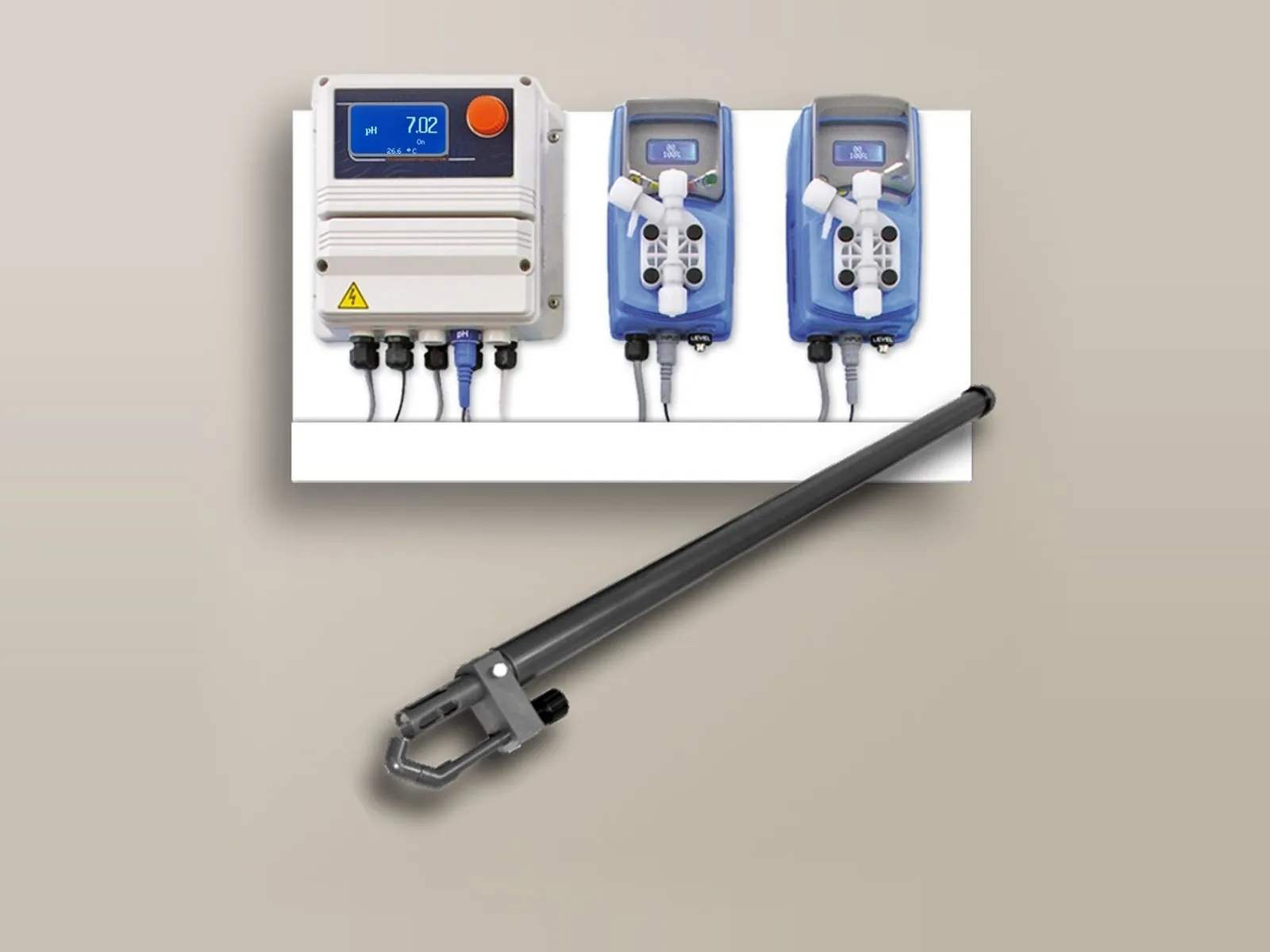
The correct pH value ensures regulatory compliance and optimal operating conditions for all materials in contact with the water. The LDspH system measures the pH and controls the dosing pump, which injects acid or base in proportion to the measured value up to the set pH (set point).
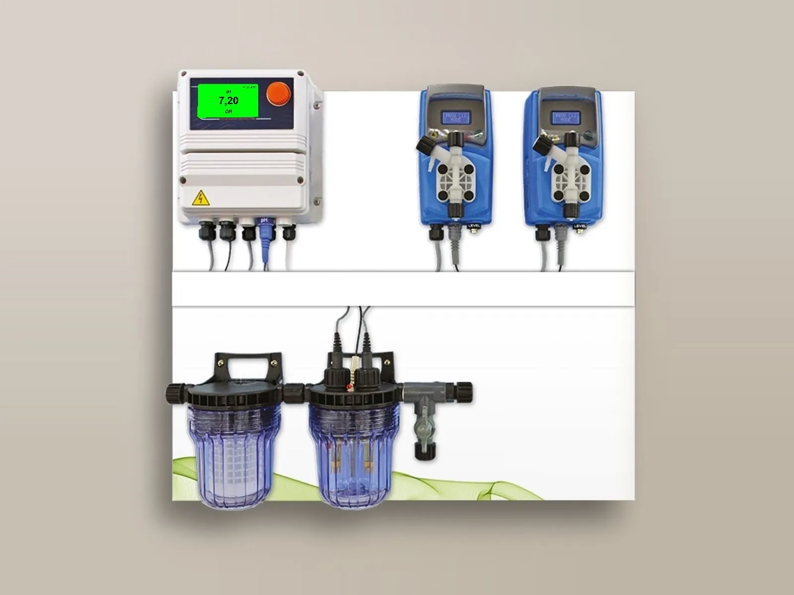
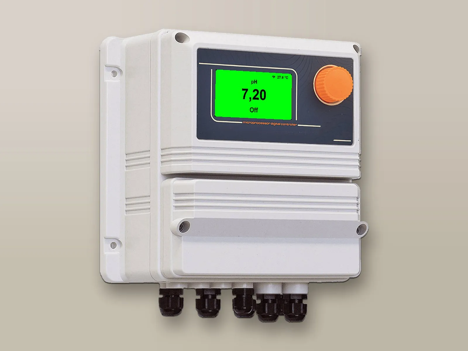
For wastewater, domestic water, drinking water, process water or swimming pool water: the required pH is set and the system maintains it automatically.
Insight: controlling the pH of water →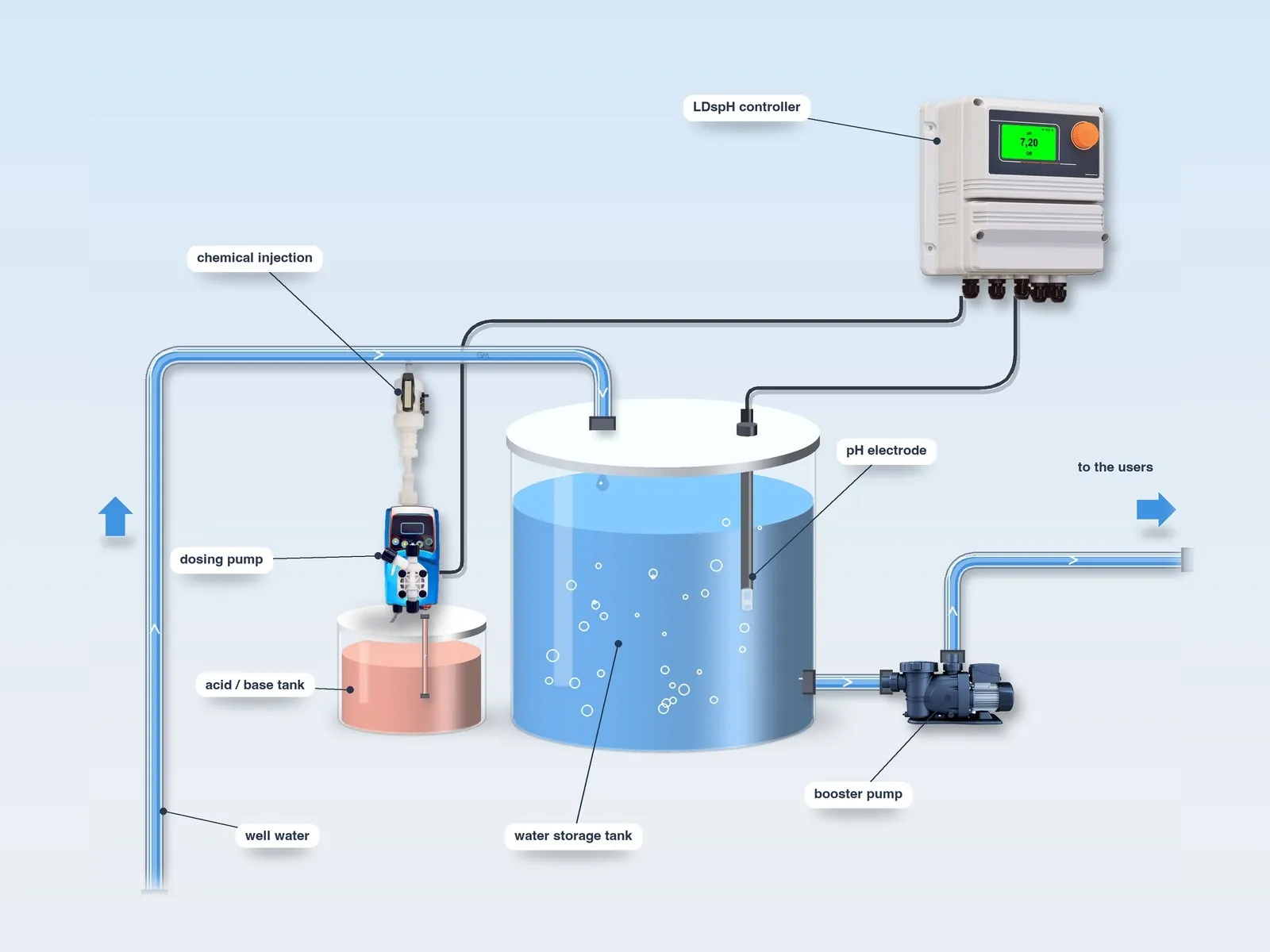
The electrode continuously detects the pH of the water in the tank or in the pipe.
The controller activates one or more dosing pumps that inject the pH corrector (acid or base) into the tank or pipe, in proportion to the measured pH, up to the set point.
At each draw-off, the incoming water comes into contact with the corrector and the pump doses acid or base until the set pH is restored.
By adding a pulse-output water meter and a dosing pump connected to it, dosing also becomes proportional to the volume of water treated; the controller can also drive solenoid valves or other equipment according to the measured pH.
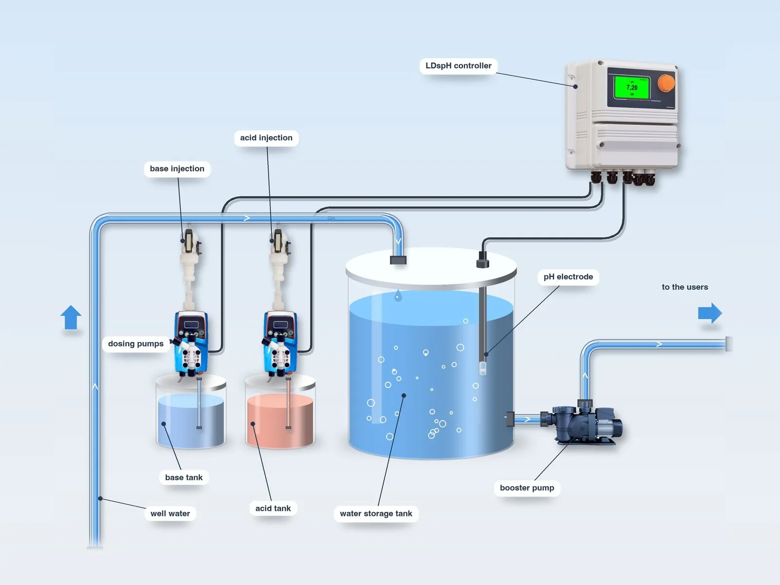
Two different substances (generally an acid and a base) can be dosed into the same tank or pipe, or the same substance into two separate tanks or pipes.
Raw water from wells and springs, private and from public water supply networks.
Insight: well water →Domestic water circuits.
Industrial process water (also with LDsPN).
Municipal and industrial wastewater (also with LDsPN).
pH measurement and control with acid or base dosing. Wide flexibility in electrode positioning: in a flow-through probe holder, in-line on the pipe or immersed in the tank.
The electrode, with a flat measuring membrane kept clean by the water flow, is mounted in an immersion probe holder with nozzle: at programmed intervals the controller opens a solenoid valve that sends a jet of water or compressed air onto the electrode, removing deposits. During cleaning the pump outputs are disabled.
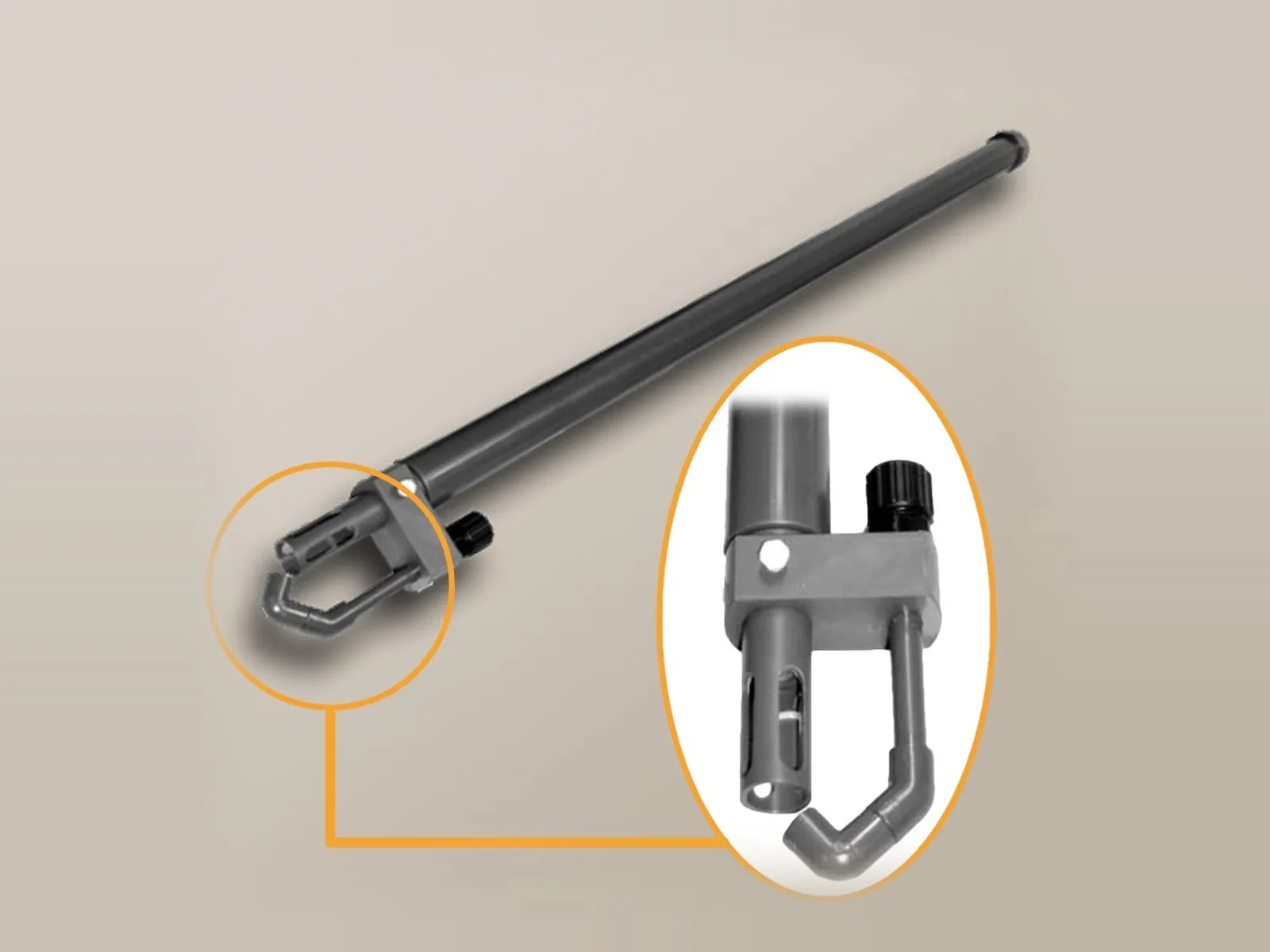 PECAPImmersion probe holder with cleaning nozzle.
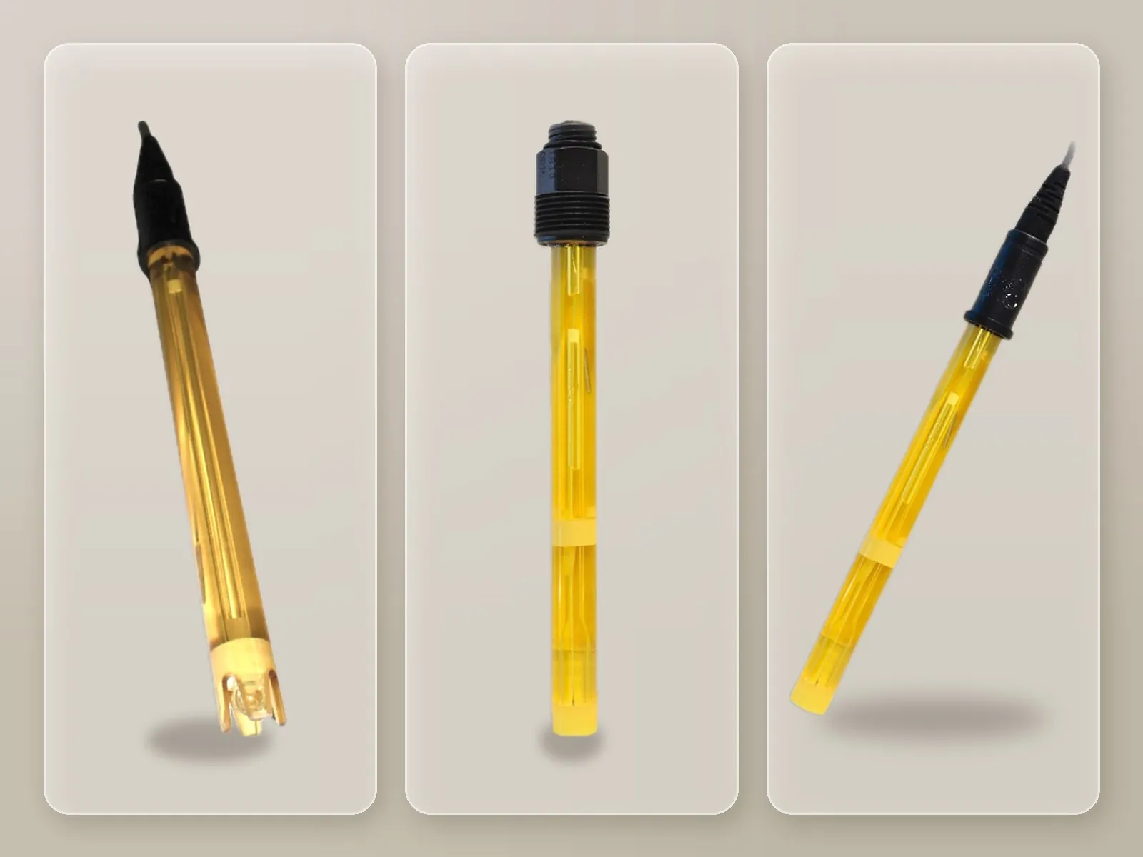
Single or double junction combination electrode, resistant to acids and bases, high temperatures and hydrofluoric acid, also suitable for low-conductivity water; available in a self-cleaning version.
pH electrodes → In the immersion probe holder with nozzle, a jet of water or air keeps the electrode clean in water with a high impurity load.
Probe holders →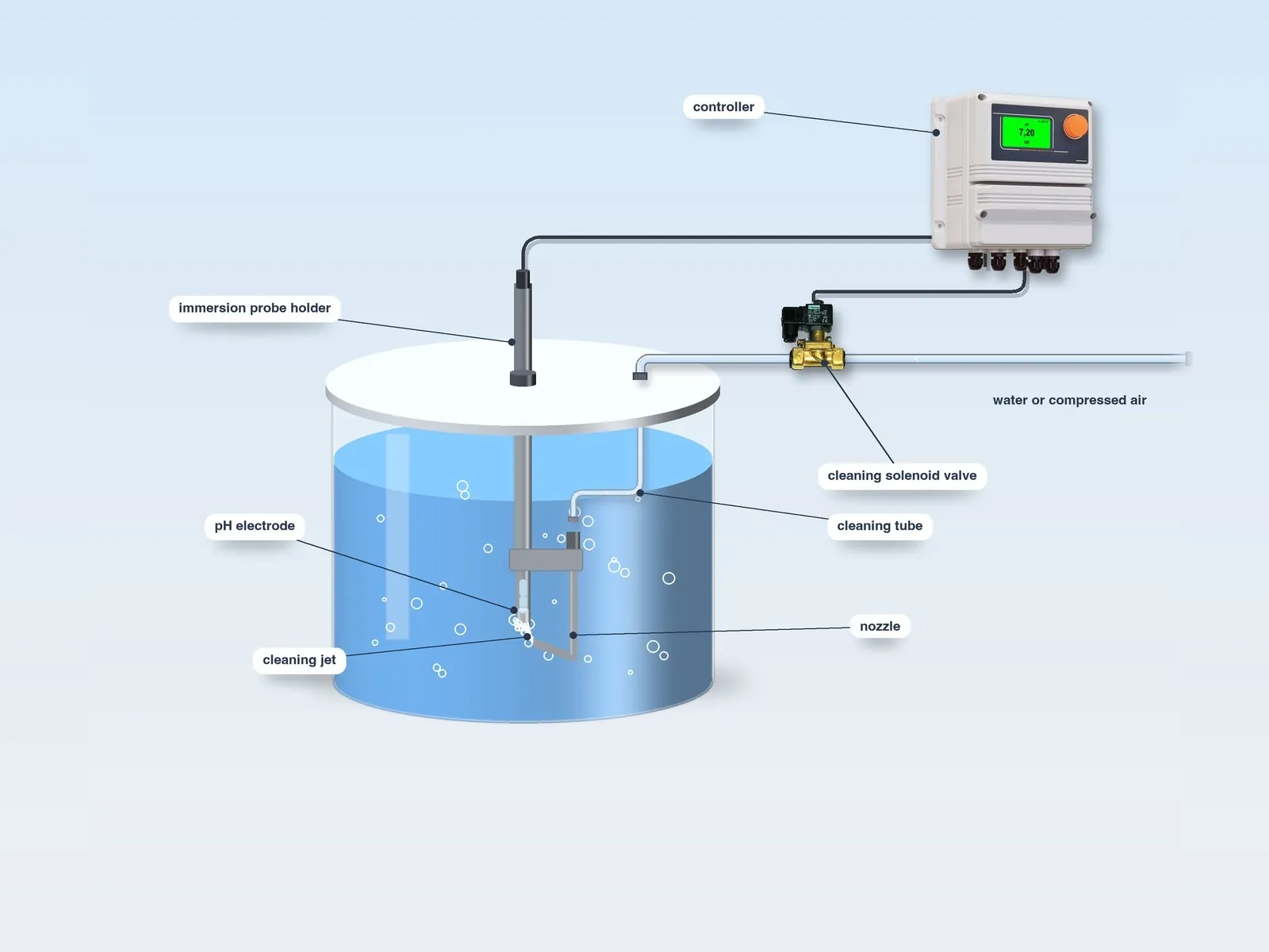
At programmed intervals the controller suspends dosing (stand-by) and opens the solenoid valve on the water or compressed air line: the jet comes out of the nozzle below the electrode tip and removes deposits. When cleaning is complete, the valve closes and, once the electrode repolarisation time has elapsed, dosing resumes.
The controller measures pH from 0 to 14 (resolution 0.01) and temperature from 0 to 100 °C (resolution 0.1 °C), with automatic compensation; electrode self-cleaning on request, standard in the self-cleaning version.
| Electrode | Pressure | Connection | Body | Minimum conductivity | Junction | Temperature | Cable | Diameter | Notes |
|---|---|---|---|---|---|---|---|---|---|
| EPHS | 7 bar (3.5 bar) | BNC | Epoxy | 100 µS | – | 70 °C (80 °C) | 0.8 m | 12 mm | – |
| EPHM | 7 bar (3.5 bar) | BNC | Epoxy | 100 µS | – | 70 °C (80 °C) | 4.5 m | 12 mm | – |
| EPHL | 7 bar (3.5 bar) | BNC | Epoxy | 100 µS | – | 70 °C (80 °C) | 15 m | 12 mm | – |
| EPHSN6 | 7 bar (3.5 bar) | SN6 with PG13.5 thread | Epoxy | 100 µS | – | 70 °C (80 °C) | 1 – 100 m | 12 mm | – |
| EPHMD/100 | 7 bar | BNC | Epoxy | 100 µS | Double | 100 °C | 4.5 m | 12 mm | – |
| EPHM/D | 7 bar (3.5 bar) | BNC | Epoxy | 100 µS | Double | 70 °C (80 °C) | 4.5 m | 12 mm | – |
| EPHM/D/SN6 | 7 bar (3.5 bar) | SN6 with PG13.5 thread | Epoxy | 100 µS | Double | 70 °C (80 °C) | 1 – 100 m | 12 mm | – |
| EPHMD/LI | 7 bar (3.5 bar) | SN6 with PG13.5 thread | Epoxy | 3 µS | Double | 70 °C (80 °C) | 1 – 100 m | 12 mm | For low-conductivity water |
| EPHSC | 7 bar (3.5 bar) | BNC | Epoxy | 100 µS | Double | 70 °C (80 °C) | 4.5 m | 12 mm | Self-cleaning |
| EPHSC/SN6 | 7 bar (3.5 bar) | SN6 with PG13.5 thread | Epoxy | 100 µS | Double | 70 °C (80 °C) | 1 – 100 m | 12 mm | Self-cleaning |
| EPHM/HF | 7 bar (3.5 bar) | BNC | Epoxy | 100 µS | Double | 70 °C (80 °C) | 4.5 m | 12 mm | Resistant to 1% hydrofluoric acid |
| EPHSN6 GK | 10 bar | SN6 | Glass | 150 µS | – | −5 / 135 °C | 1 – 100 m | 12 mm | High temperature |
All models: combination electrode, range 0 – 14 pH, resolution 0.01.
Electrode positioning is defined according to the characteristics of the installation and of the water to be analysed.
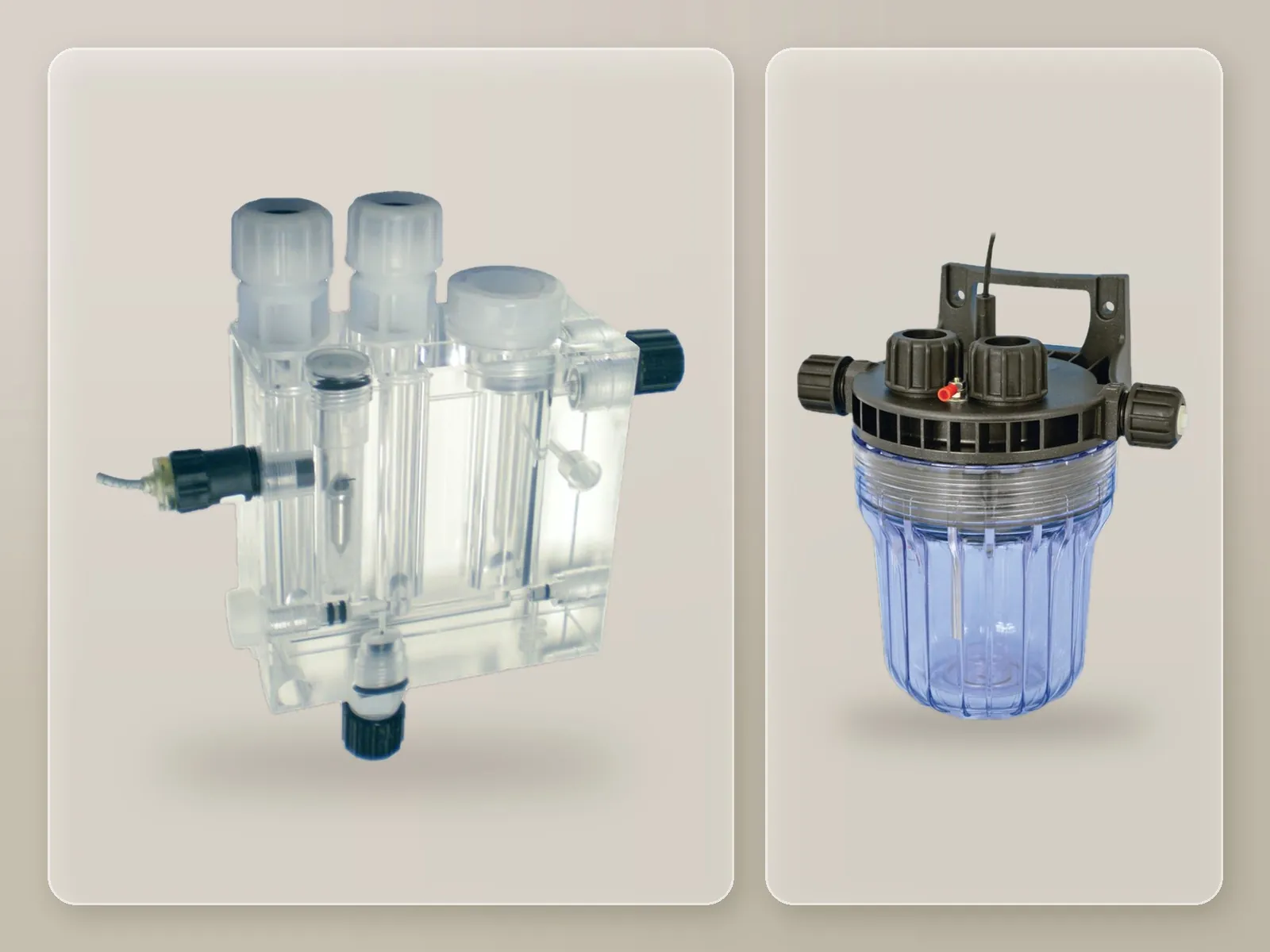
The probes are housed in a PEF flow-through probe holder or an NPED probe holder, connected to a water tapping point at the tank outlet and fed with about 30 l/h of sample water. A flow sensor can be added, which stops dosing when there is no flow.
Probe holders →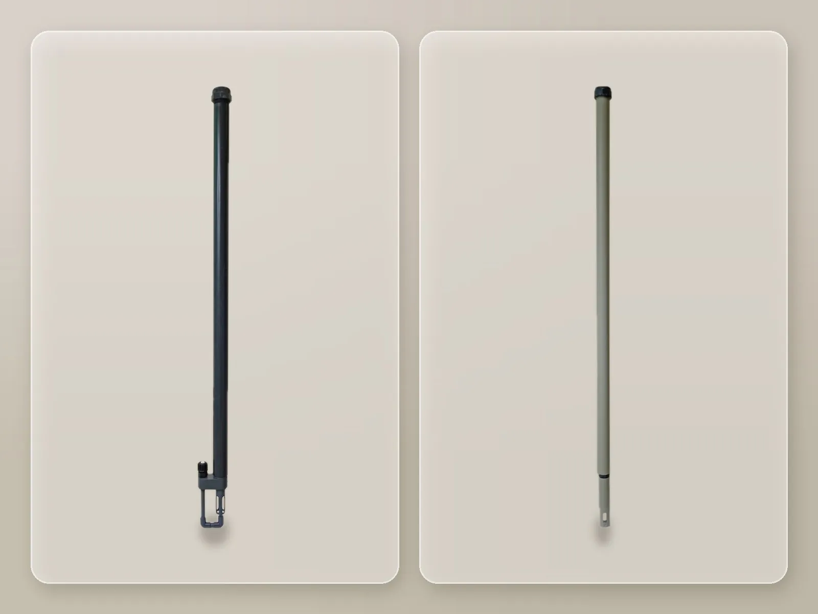
The electrode is immersed directly in the storage tank of the water to be treated, by means of an immersion probe holder.
Probe holders → A solution suited to heavily loaded water: at programmed intervals the control panel puts the controller in stand-by and opens a solenoid valve that sends water or air to the nozzle; once cleaning is complete, it closes the valve and, after the electrode repolarisation time has elapsed, resumes dosing.
Probe holders →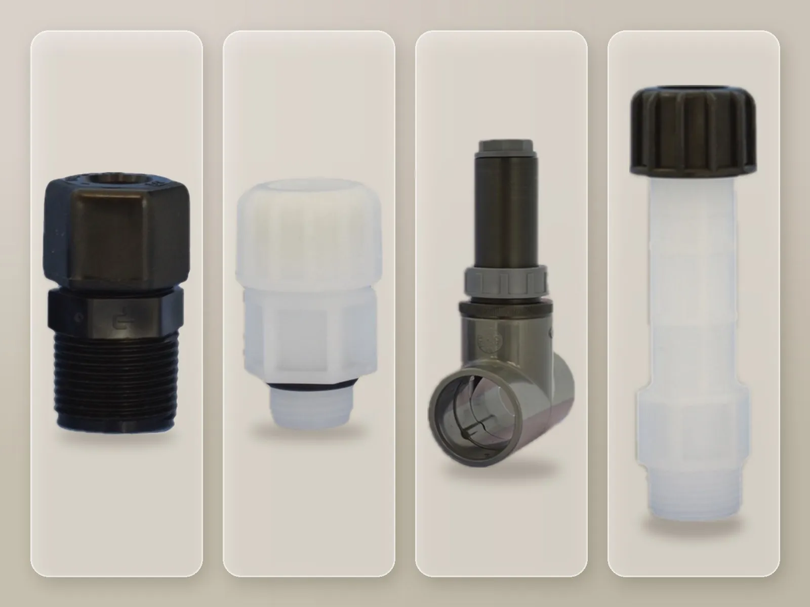
The electrodes are inserted directly into the pipe carrying the water to be treated.
Probe holders →It acquires the measurement from the probe and drives the dosing pump in proportion to the value detected. It is supplied pre-assembled on a panel, ready for connection.
Multicolour backlit display that indicates the different operating states by changing colour. Programming via a single knob.
Proportional, ON/OFF, PWM and PID dosing, with delayed dosing start.
Permanent data storage and a system log viewable on the display; the internal log can be exported to a USB memory stick for processing with a spreadsheet.
Chemical level, no flow, maximum dosing time exceeded, probe failure, out-of-range reading; acoustic or visual signalling via the alarm output.
The dosing pump, with flow rate and back-pressure defined at the time of ordering, is connected to the pulse output (and/or 0-4/20 mA) and operates in proportional or ON/OFF mode. A pre-calibrated injection valve and a magnetic level probe with coaxial foot filter, which stops the pump when the chemical runs out, are supplied as standard.
By changing colour, the controller’s backlit display indicates the different operating states, which can be recognised even from a distance.
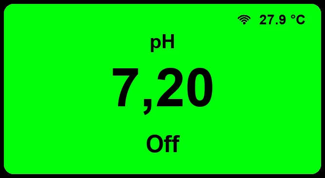
Measurement and dosing according to the set parameters.
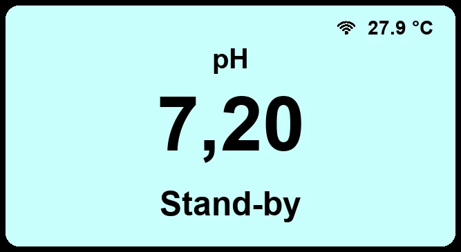
Controller in stand-by.
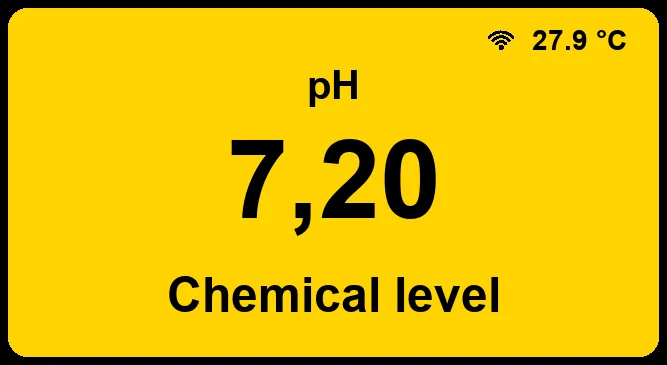
Warning signal, for example the chemical level.
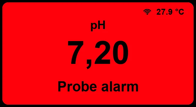
Alarm signal, for example from the probe.
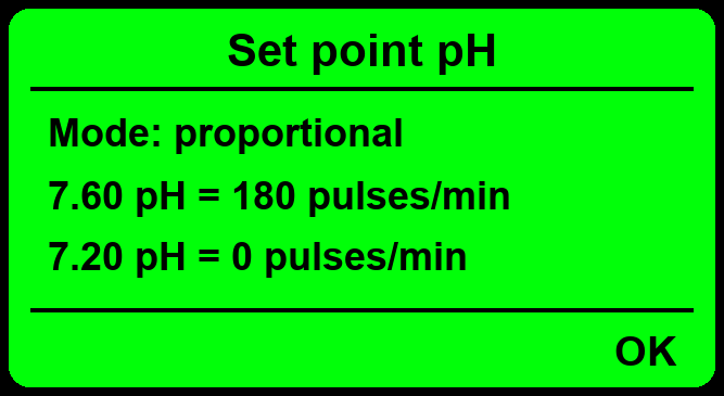
Inputs, outputs, control modes and alarms of the controller.
Fully programmable automatic system for the pH neutralisation of process water and wastewater in a tank: it manages the inlet and drain valves, the mixer and the acid and base dosing pumps. The cycle phases are repeated at each activation signal. Two modes: neutralisation to the set pH, or alkaline precipitation (for example of heavy metals) at a settable pH, with reaction time, followed by neutralisation.
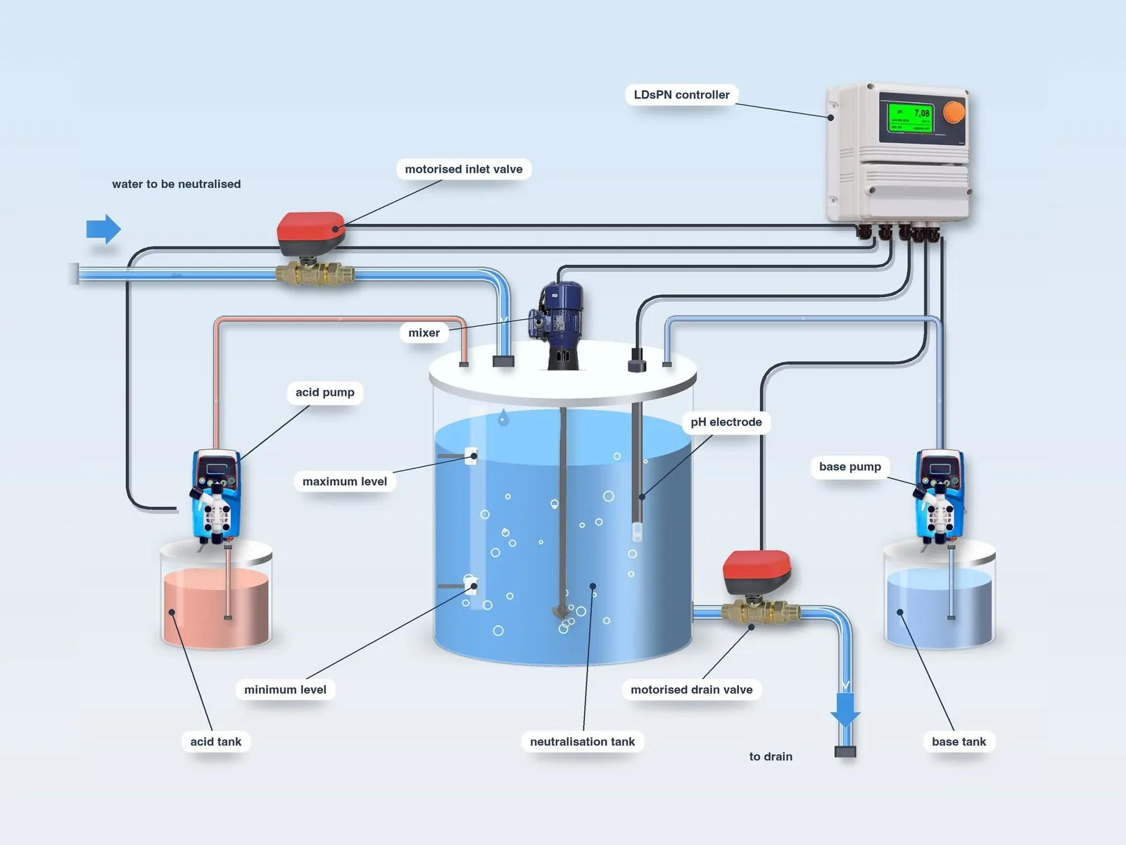
Control of the water level in the tank.
Opening of the inlet valve and closing when the set level is reached.
pH measurement by means of the electrode.
Dosing of acid or base for neutralisation, with dosing pump and mixers running.
Waiting for the set reaction time.
Opening of the drain valve and emptying of the tank.
Repetition of the cycle at each activation signal.
The display shows the cycle phases and is used to set set points and times.
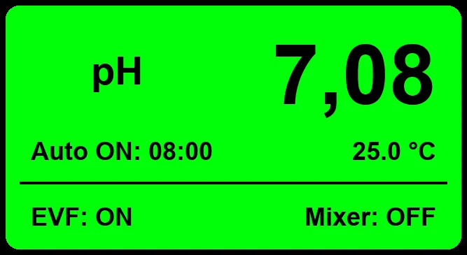
Measured pH, automatic mode with cycle start at the programmed time, temperature, status of the inlet valve (EVF) and of the mixer.
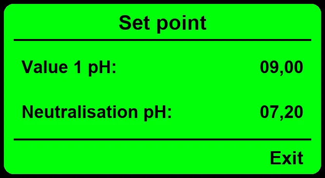
Neutralisation: Value 1 pH and neutralisation pH coincide. Alkaline precipitation: base is dosed up to Value 1 pH, then acid up to the neutralisation pH.
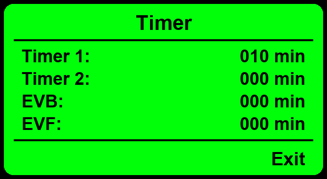
Reaction times (Timer 1 and 2) and filling and draining control times (EVF, EVB): if the level does not switch within the set time, the alarm is triggered. From 0 to 999 minutes.
Inputs, outputs, control modes and alarms of the neutralisation controller.
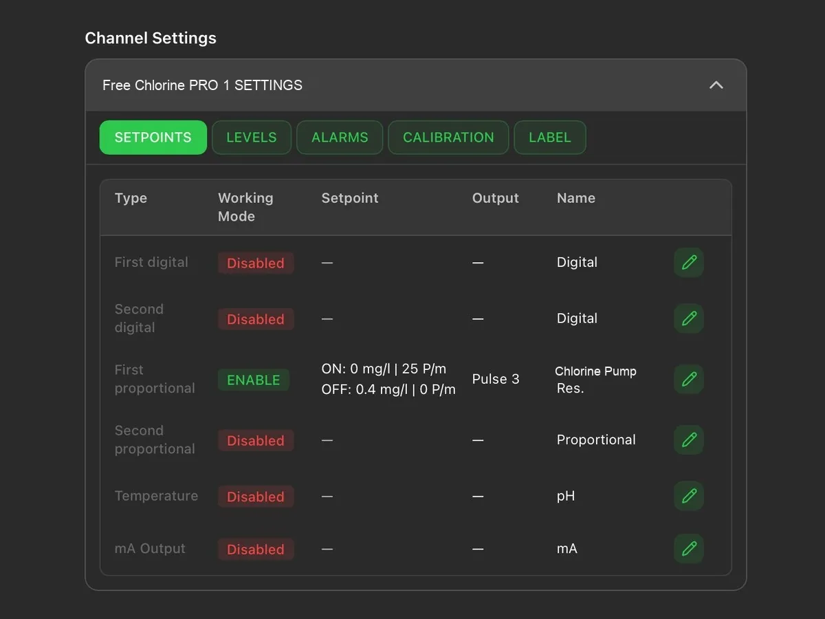
The controllers can be remotely controlled bidirectionally (read and write) from the web portal, from PC, tablet and smartphone: viewing of measurements, modification of set points, dosing and alarms, receipt of alarms and download of logs. Alternatively, integration into your PLC via Modbus is possible.
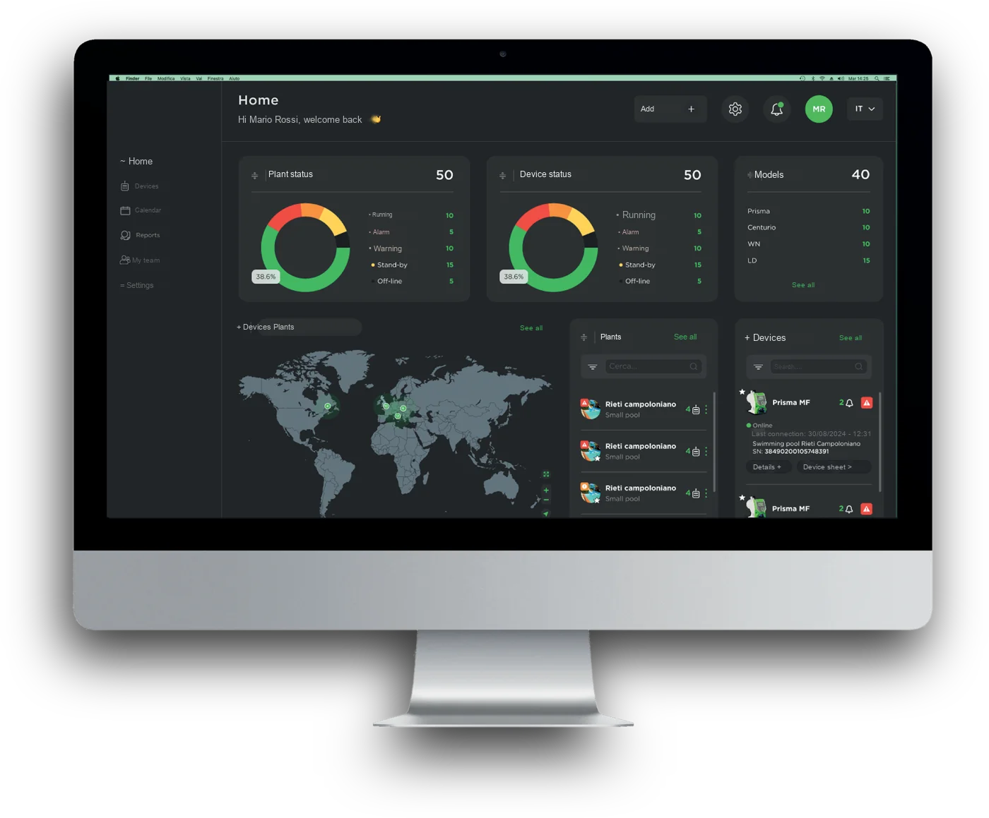
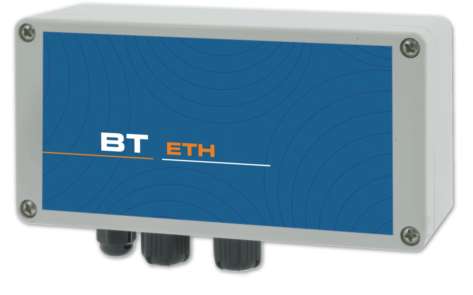
Connection to the web portal via network cable: measurements, set points, dosing and alarms accessible from PC, tablet and smartphone.
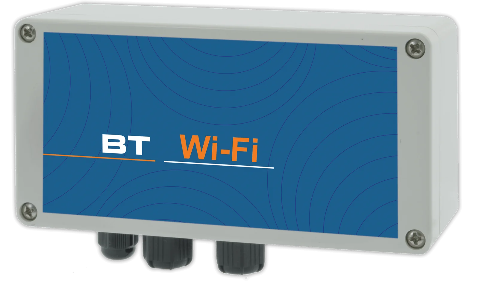
Wireless connection to the web portal, with the same functions as the cable connection.
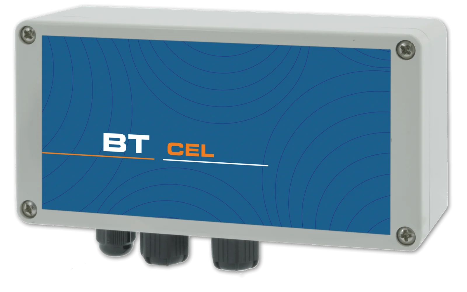
Connection via the cellular network for installations without a local network, with alarm notification by SMS or e-mail.
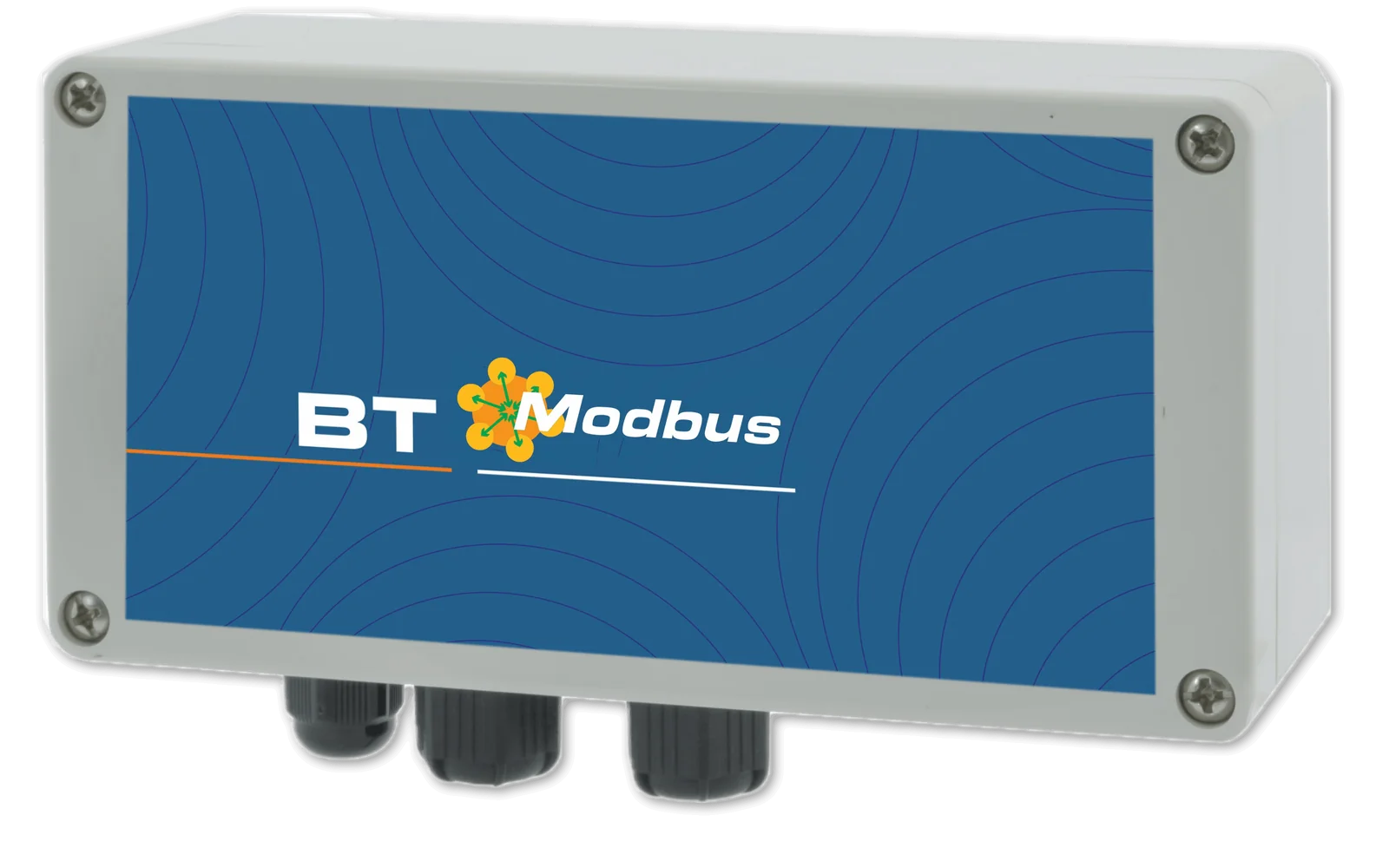
Integration into your PLC via serial port.

Current signal proportional to the measured value, for remote monitoring or for controlling pumps and other instrumentation.
One communication type at a time: Ethernet, Wi-Fi, 4G or Modbus RTU (built into the standard versions, optional on the PLUS versions). 4/20 mA outputs and meter input standard on the PLUS versions, optional on the standard versions.
A single account brings together all registered installations, each with its own devices: the web portal, free of charge and with no subscription, can be accessed from PC, Mac, tablet and smartphone and allows every parameter to be both viewed and changed, with an encrypted connection and protected access.
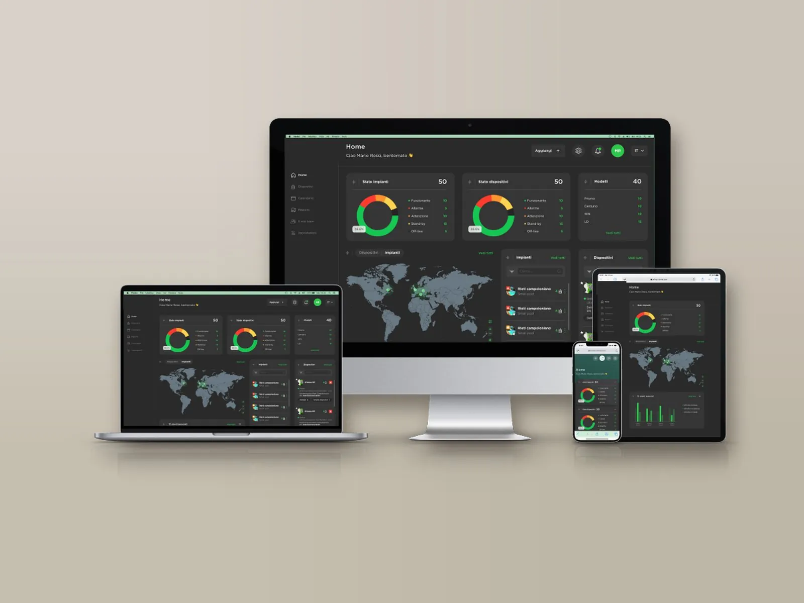
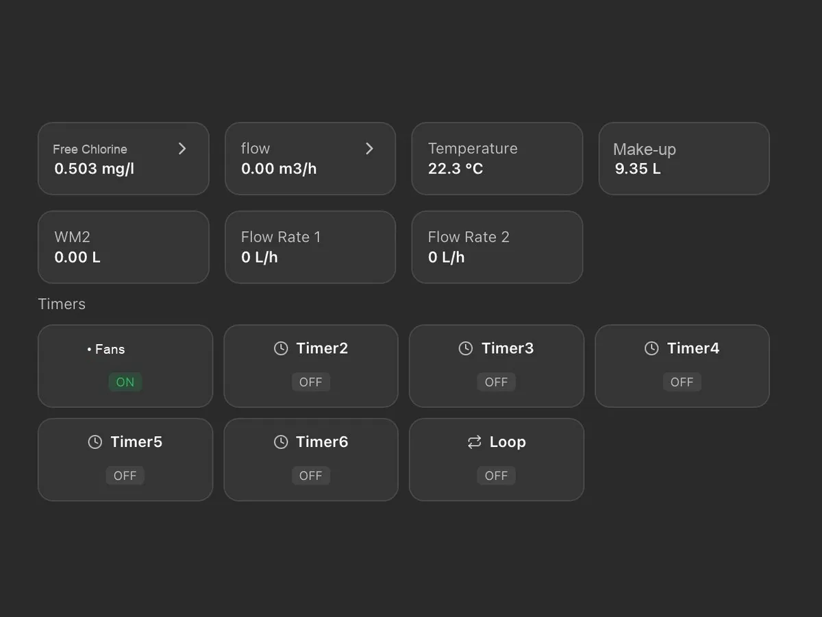
On a single screen: probe readings, chemical levels, pump activation thresholds and active alarms, with the status of installations and devices (normal, warning, alarm, standby, not connected).
Installations appear on an interactive map with their status and open with a click; for each one, the local weather conditions and temperature are also shown.
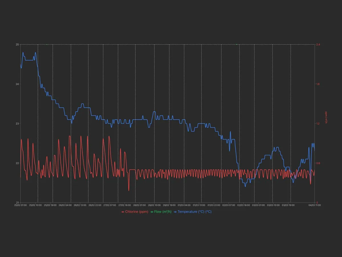
Archive of measurements and alarms, available for consultation at any time with charts and numerical reports exportable in Excel format.
Alarm thresholds for readings, dosing, faulty probe and out-of-range readings, with notification by e-mail or SMS depending on the communication system; a warning is also issued when an installation remains disconnected beyond the set time.
Remote modification of the set points, of the dosing pump activation thresholds and of the corresponding hourly flow rate.
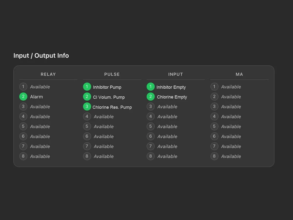
Status of relays, pulse outputs, digital inputs and current outputs, with the name assigned to each connection.
Tasks are scheduled by installation or by device and assigned to technicians; a reminder is sent by e-mail two days before the due date. Each task is shown as scheduled, due, overdue or completed.
The main account has full access and creates the technicians’ accounts, each enabled only for the assigned installations and devices; the last login and activity of each technician are visible.
Reports on devices, tasks and technicians, downloadable in PDF or CSV with the customer’s logo; the log keeps the history of operations and disconnections.
Logo, main colour and light or dark theme; the tiles on the main screen can be rearranged by dragging them. Two installations can be displayed side by side for comparison.
Each device is added through a guided procedure: the model is recognised automatically and associated with the installation, together with the technician to be contacted.
As an alternative to the portal, the Modbus RTU or TCP/IP port allows integration into the plant supervision system.
Accessories available on request to adapt the system to the requirements of the installation.
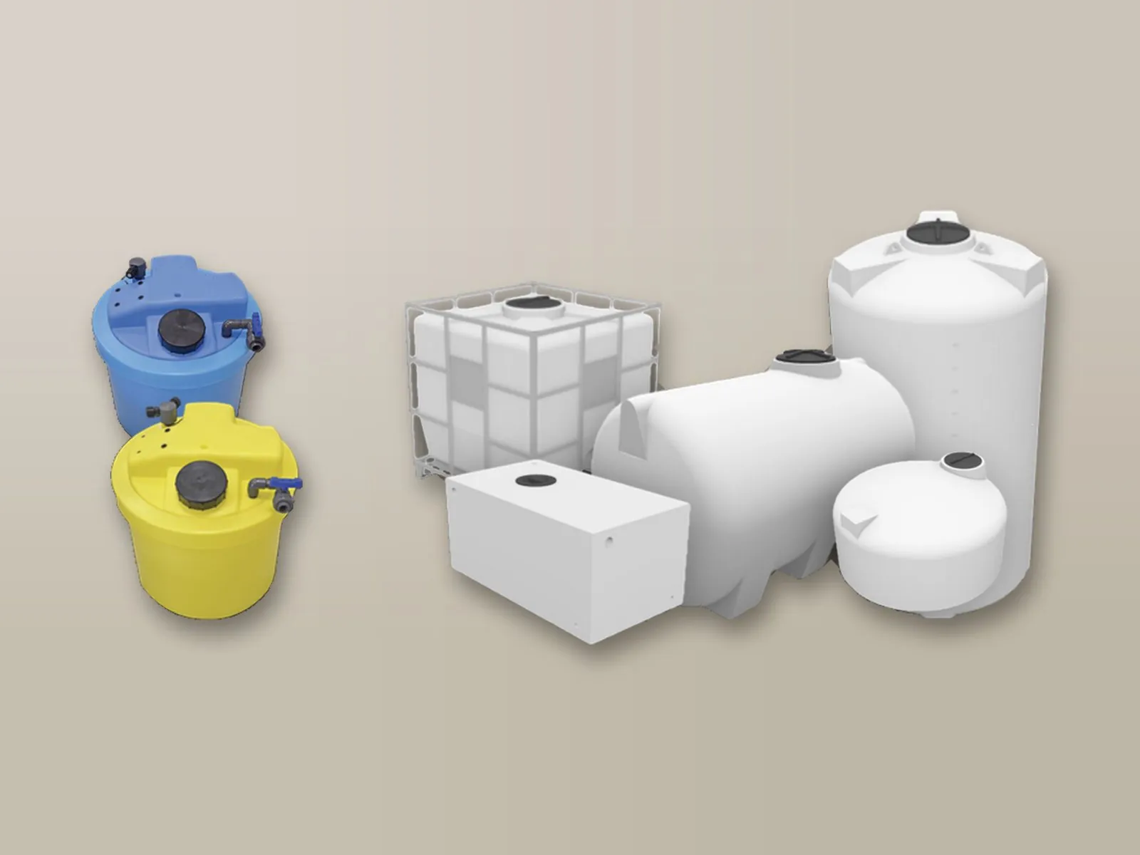
PE tanks for the chemical, with safety bund.
Details →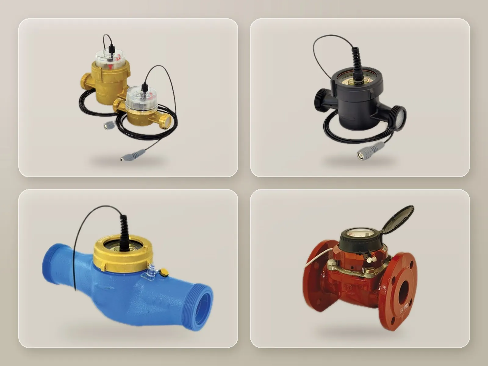
Enables dosing proportional to the volume of water actually treated.
Details →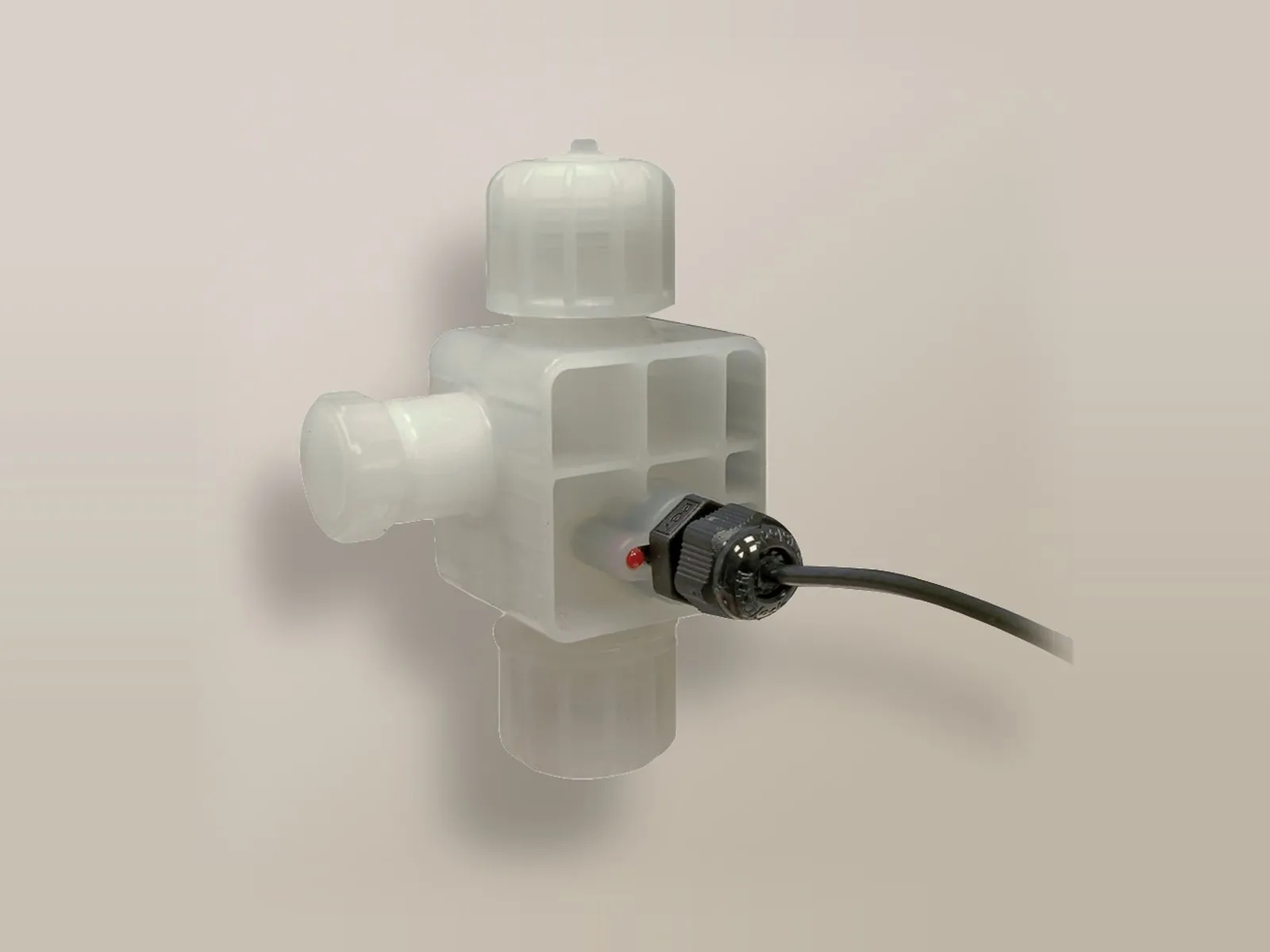
Installed on the pump delivery line, it verifies that dosing actually takes place.
Details →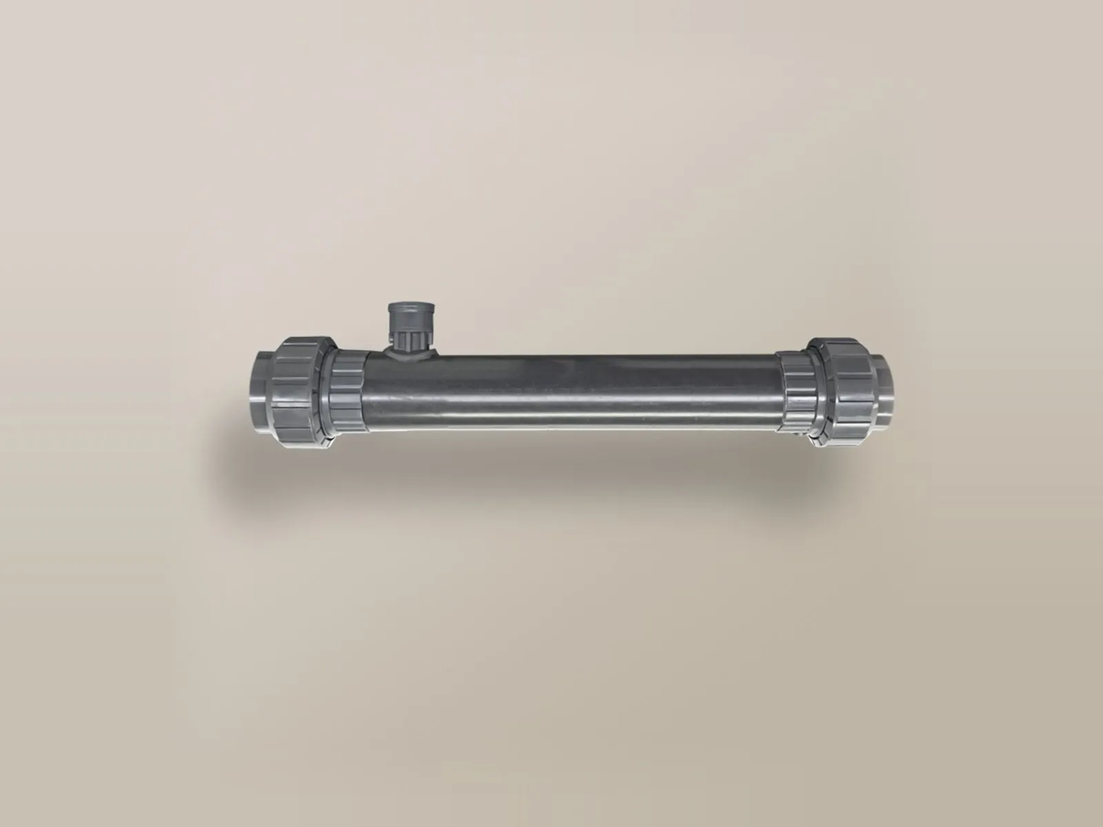
Ensures the chemical is mixed with the water and protects the pipe from direct contact.
Details →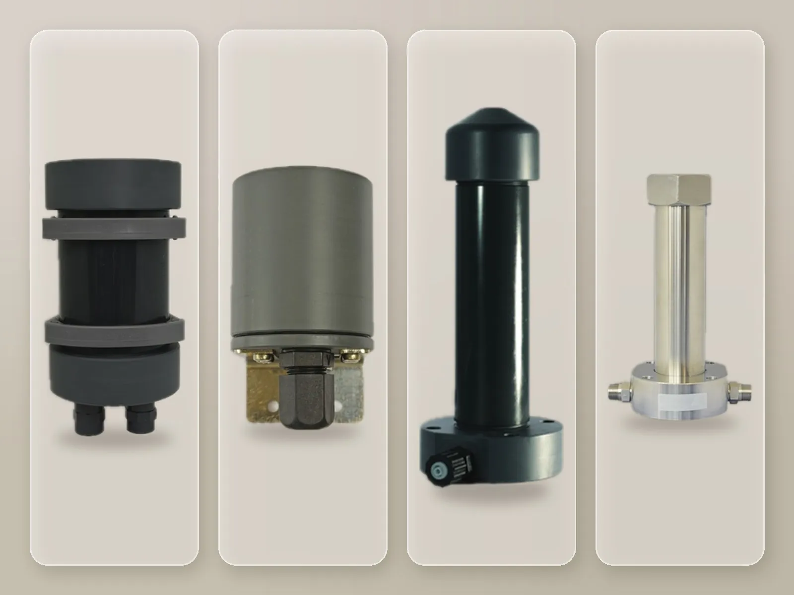
Attenuates the pulsations generated by the dosing pump.
Details →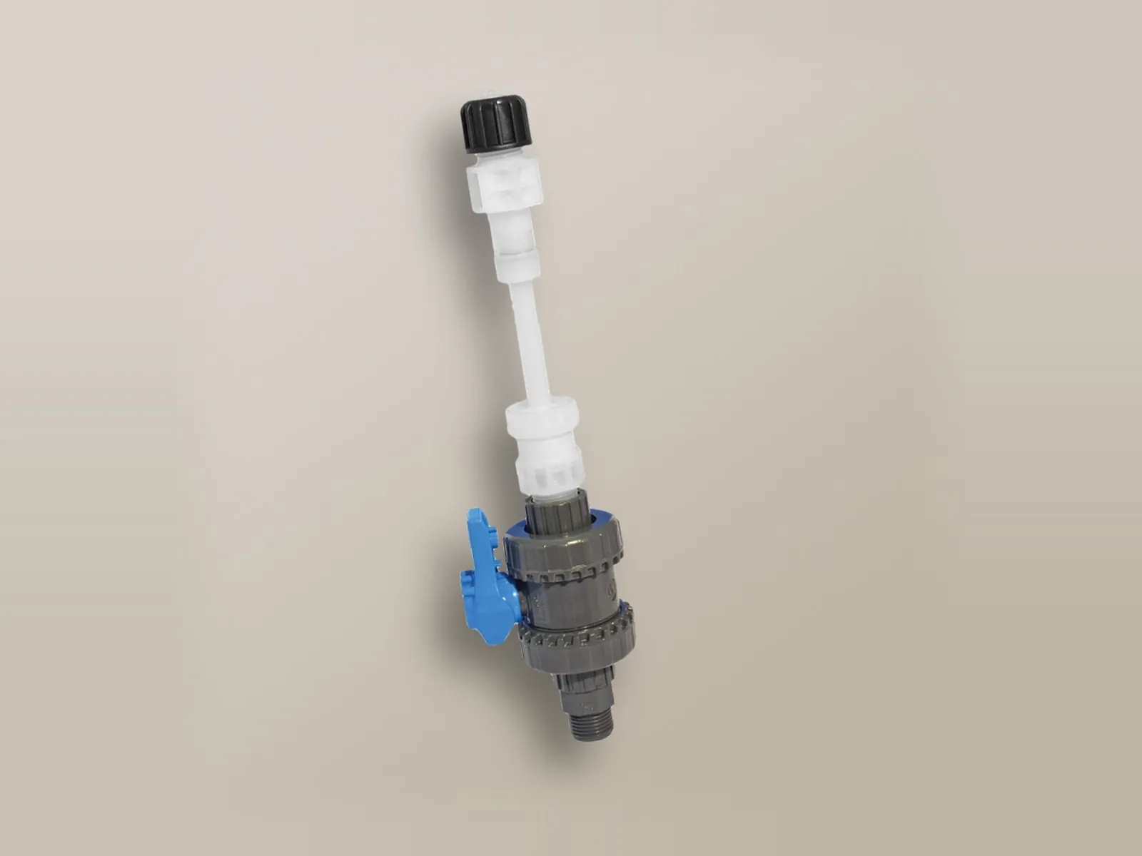
Injects the chemical into the centre of the pipe.
Details →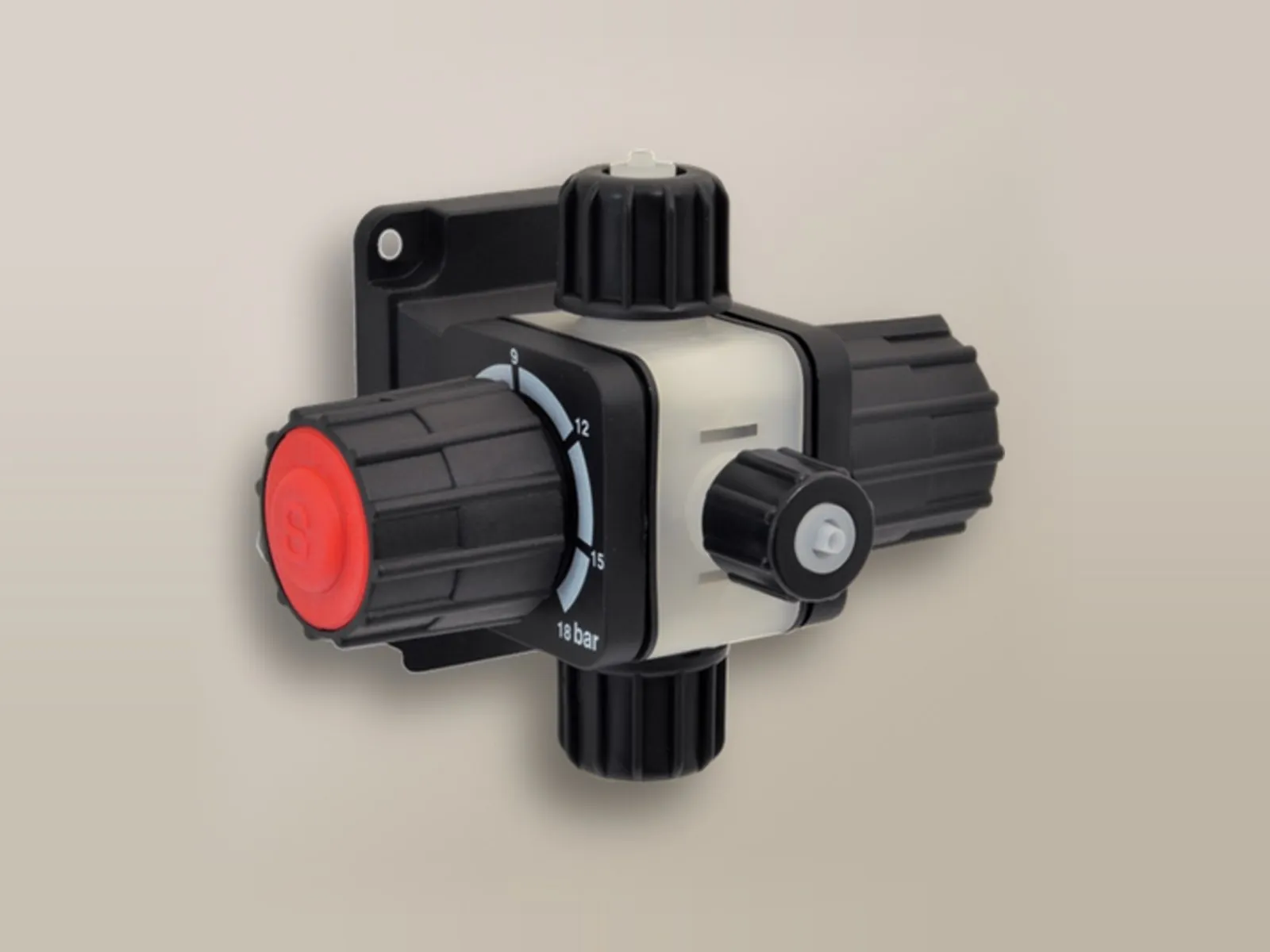
Pressure, safety and anti-siphon functions combined in a single valve.
Details →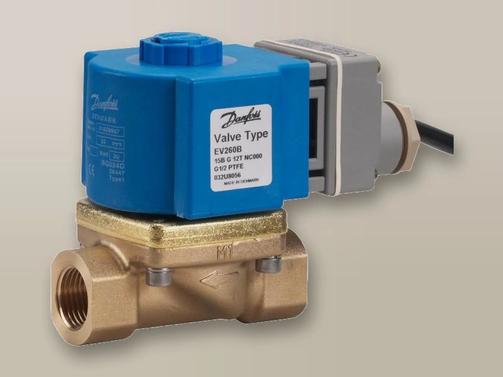
Operated by the controller according to the measured value.
For pH control the basic solution is the dosing station; when dosing has to be controlled by the measured value, measuring controllers are used.
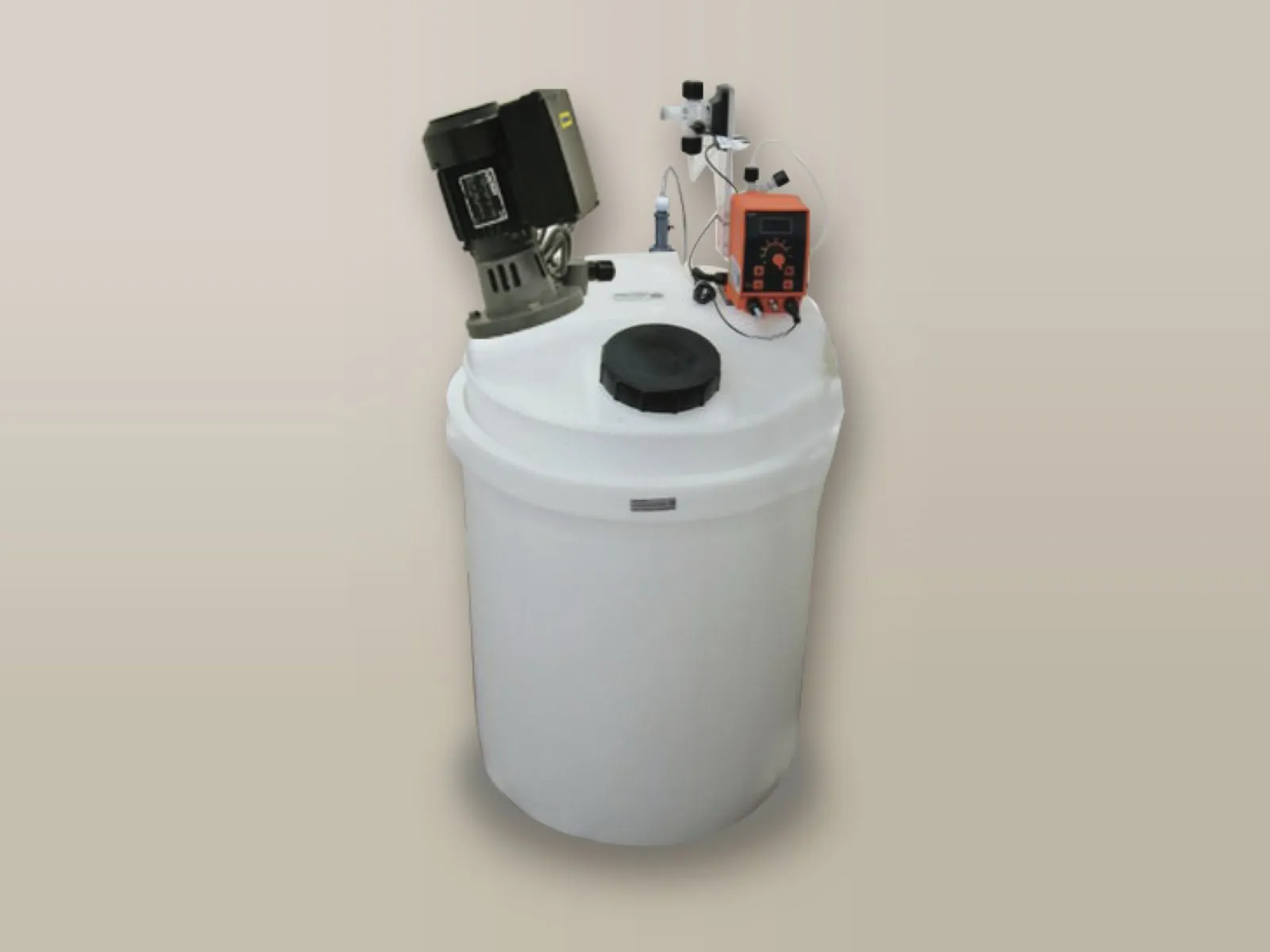
The simplest solution: the pump doses at a constant rate or in proportion to the volume of water measured by the pulse-output water meter.
Details → pH measurement and dosing of acid or alkali up to the set value.
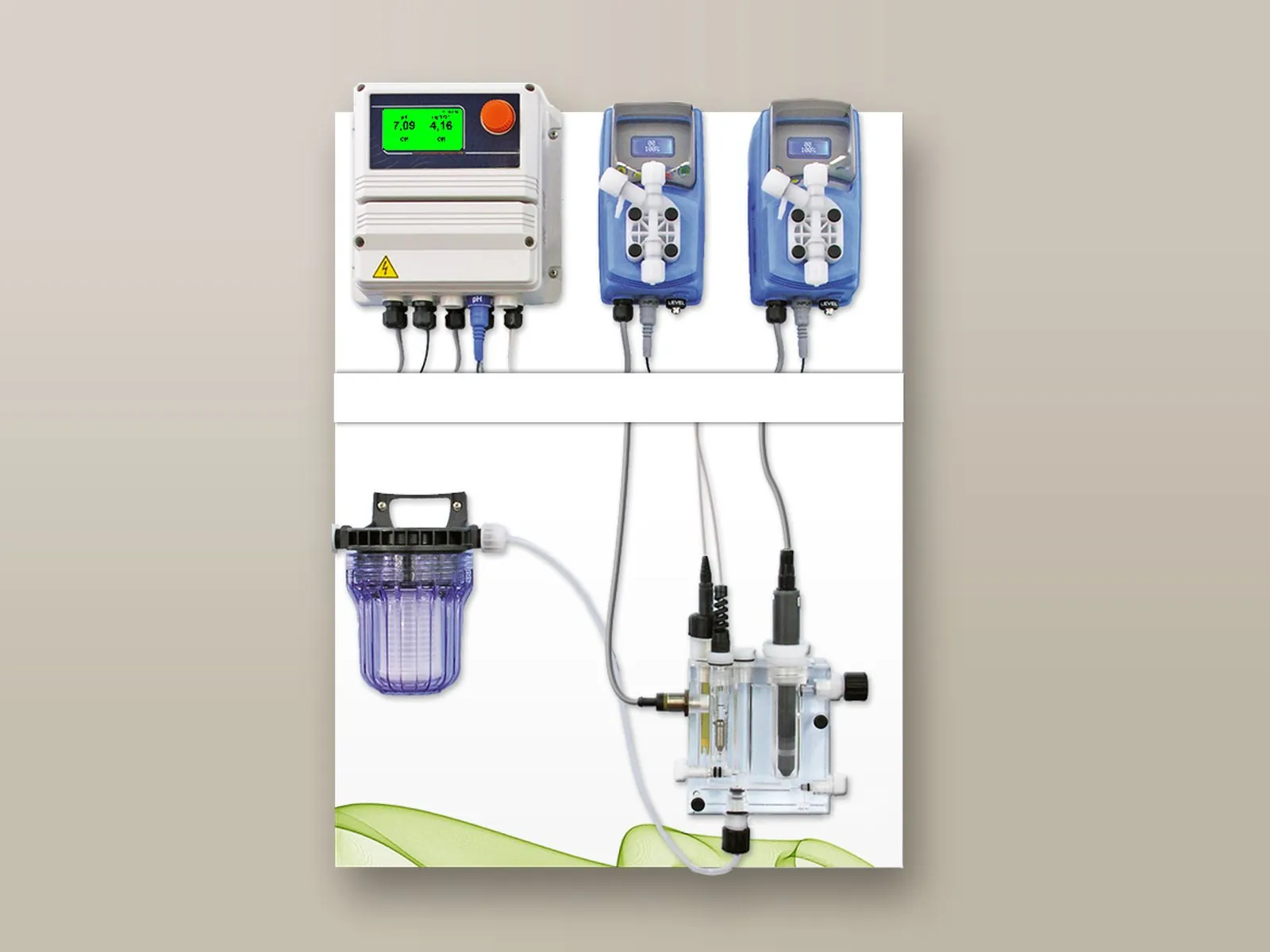
Simultaneous management of two parameters, for example pH and chlorine, with a single controller.
Details →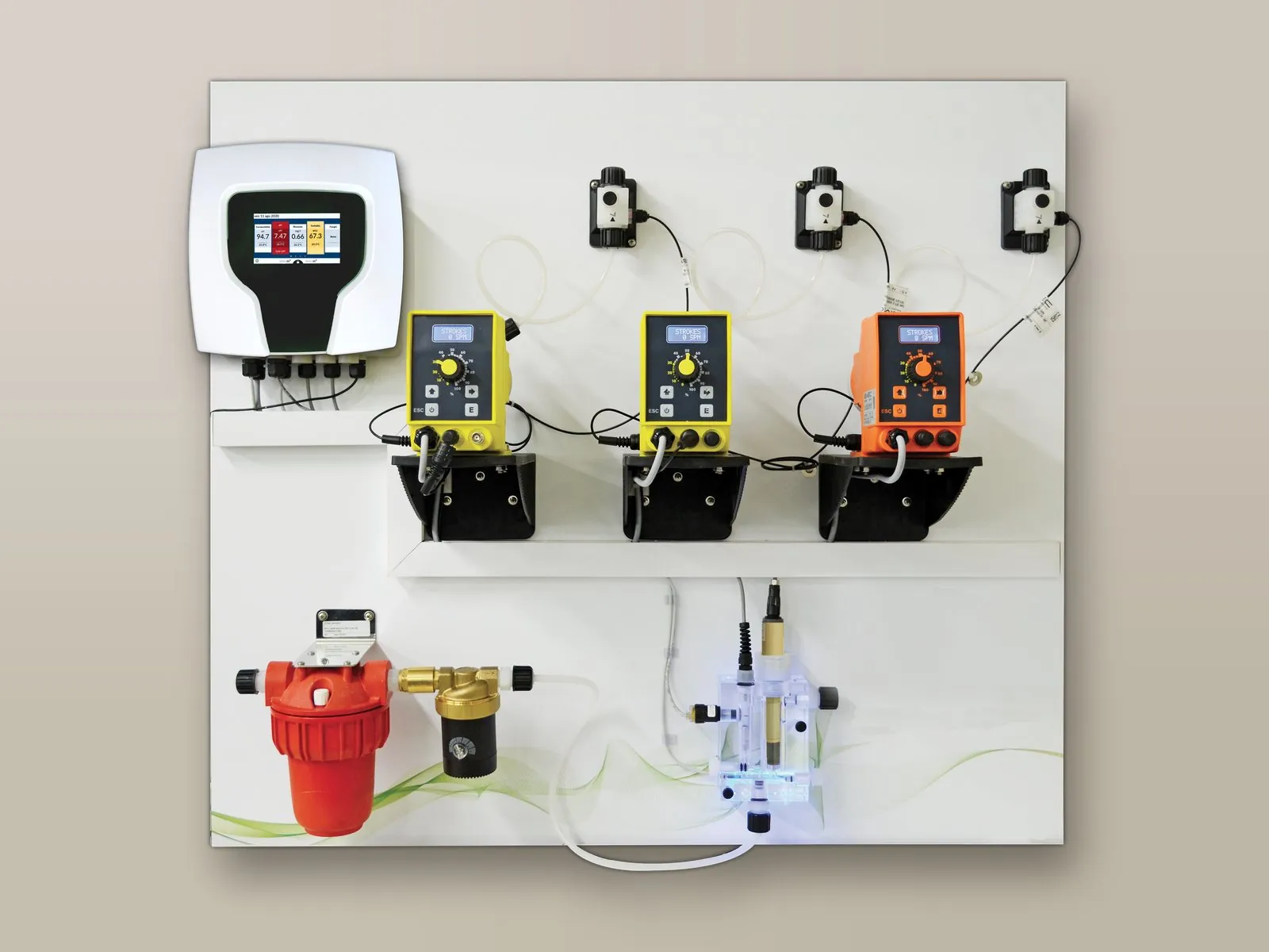
Management of up to 10 parameters and of all the pumps in the installation, with touch screen and remote control as standard.
Details →Tell us the type of water, the volumes to be treated and the pH corrector used: we will propose the most suitable electrode, probe holder, pump and accessories.
Call or write to us: a technician will reply with a tailored proposal of controllers, pumps, probes and accessories.