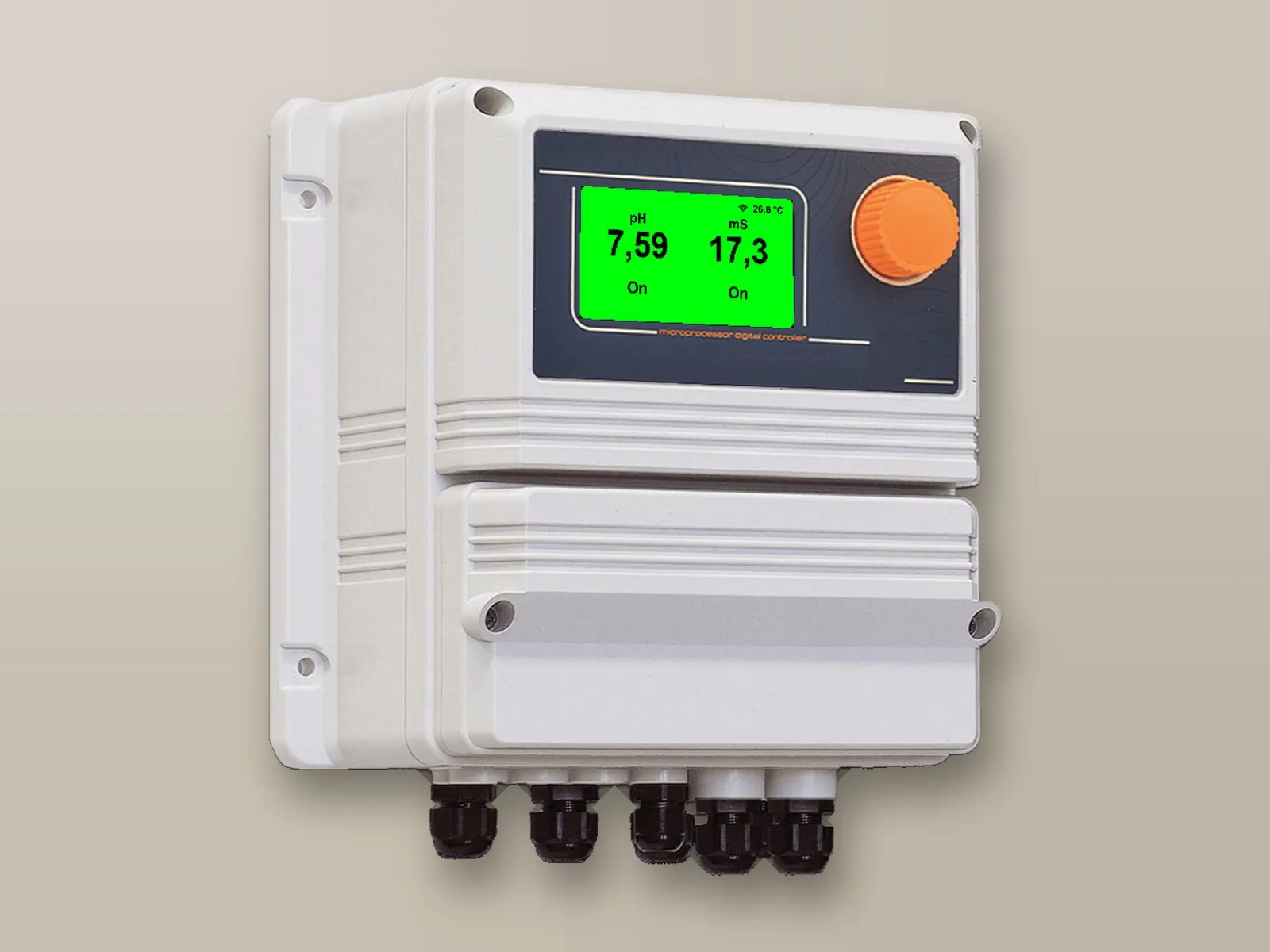
LDpHCD controller
Two-channel controller: proportional pH adjustment and ON/OFF conductivity control.
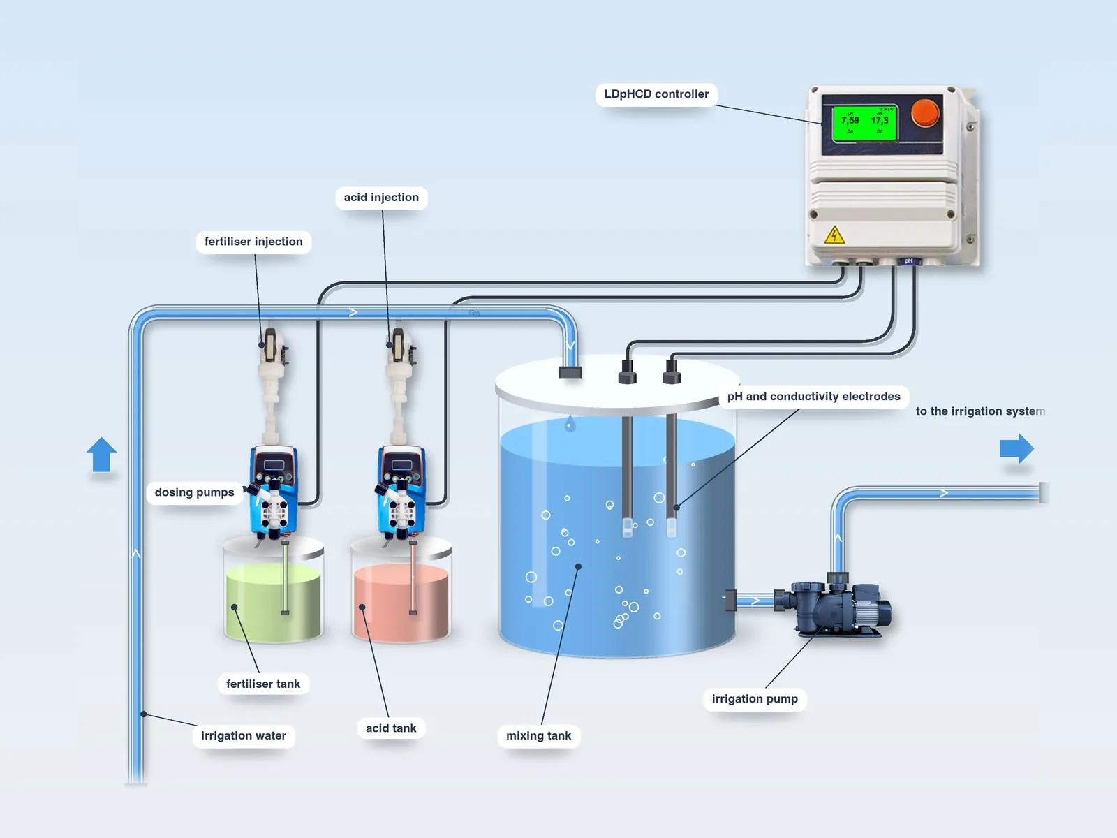
LDpHCD controller →A single controller for the two fertigation parameters: the LDpHCD adjusts the pH proportionally with acid and the conductivity with fertiliser.
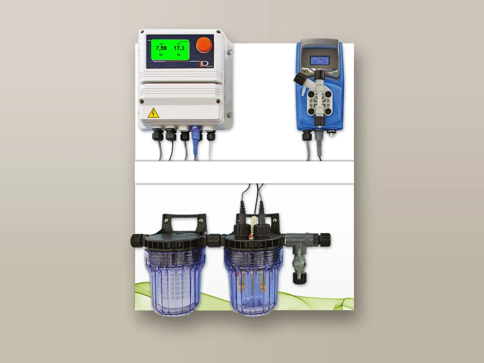
Two-channel controller: proportional pH adjustment and ON/OFF conductivity control.
LDpHCD controller →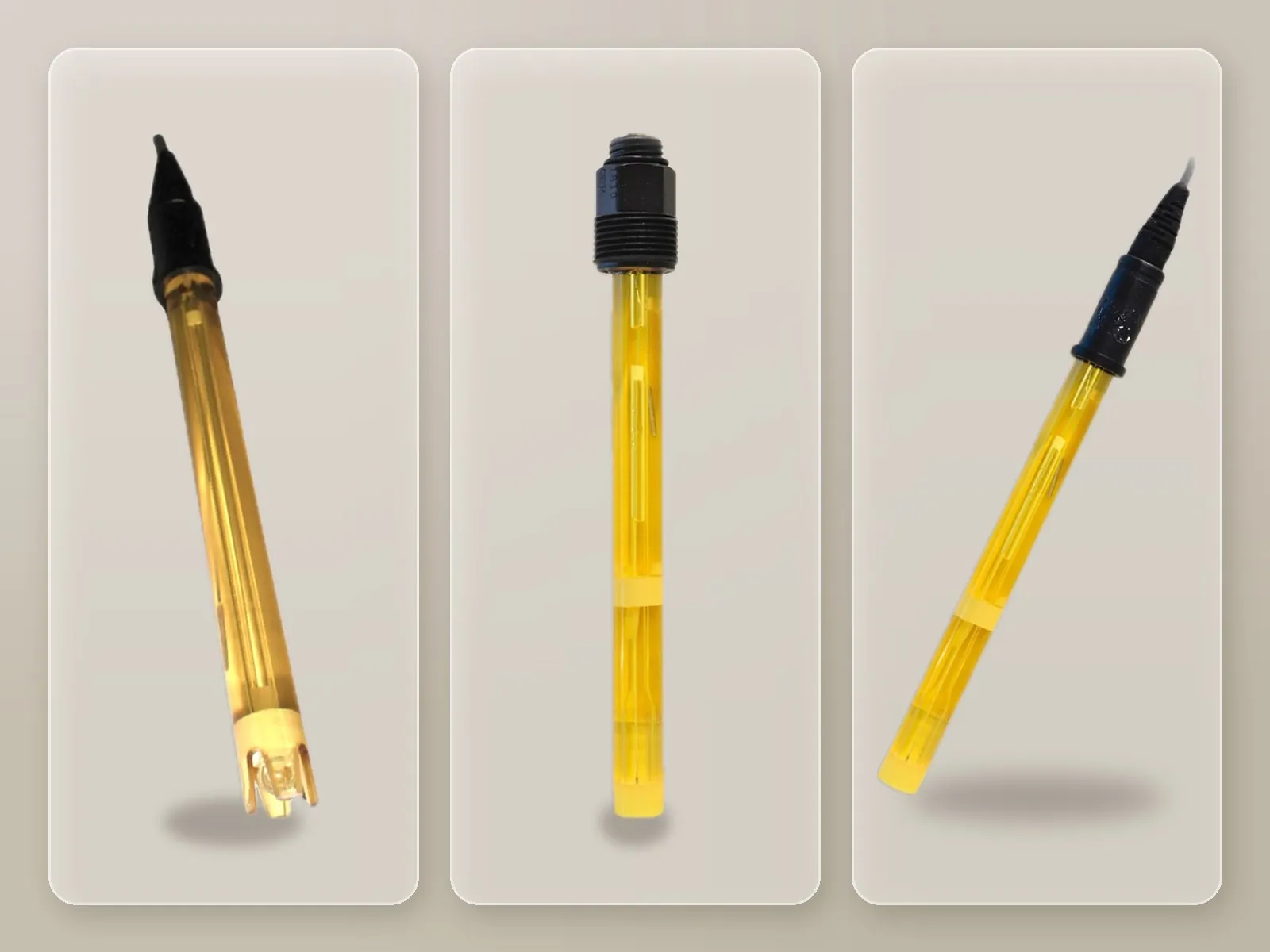
Combination electrode, 0 – 14 pH scale, with temperature compensation.
pH electrodes →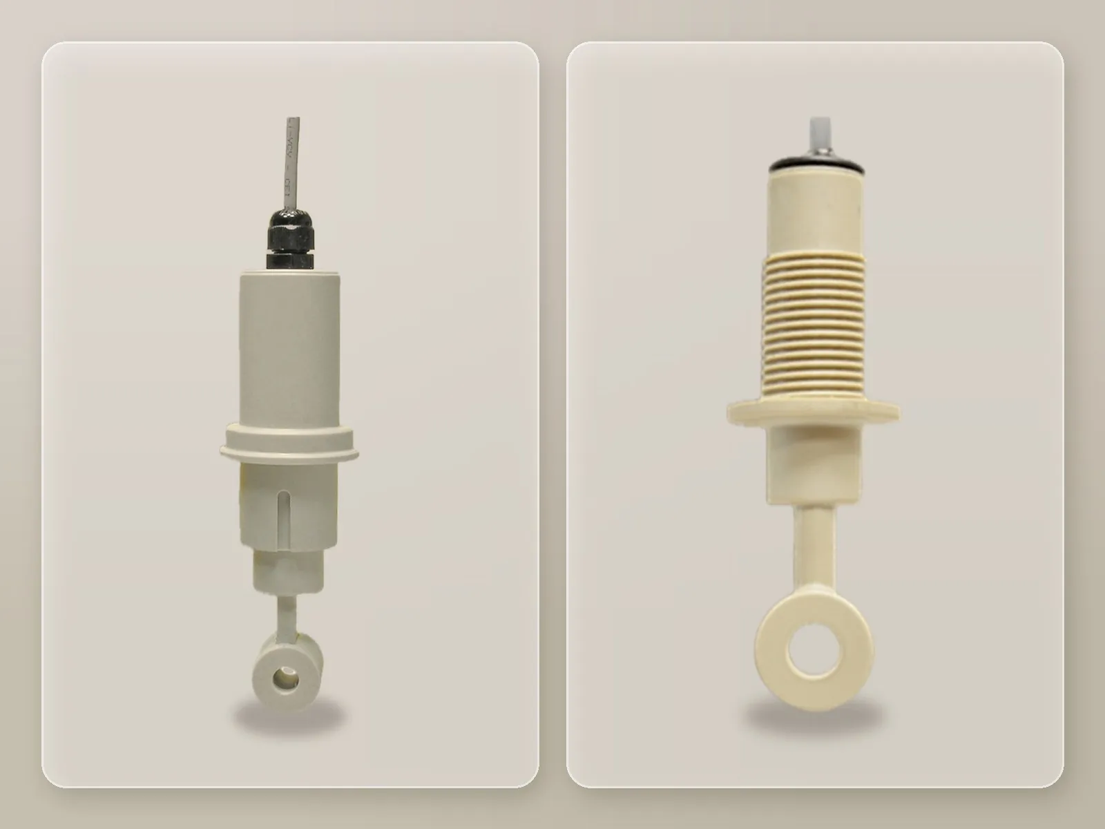
Conductive or inductive, depending on the measuring range and the water quality.
Conductivity probes →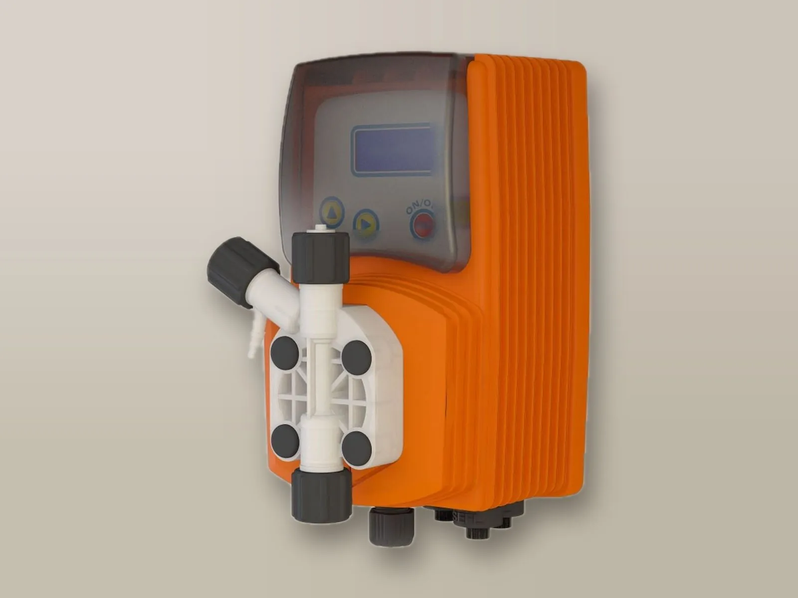
Solenoid dosing pump with adjustable flow rate, controlled by the controller or by the pulses from the water meter.
Dosing pumps →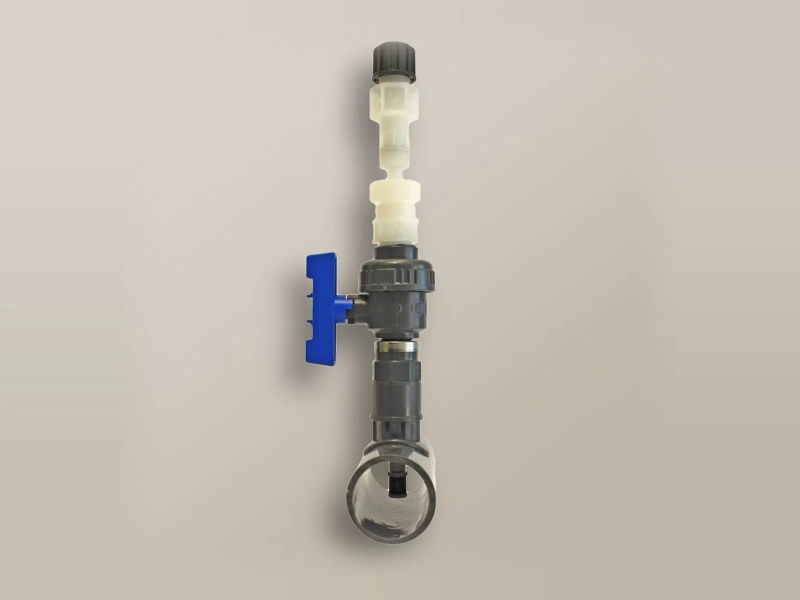
It introduces the product into the centre of the pipe, improving mixing; it can be withdrawn with the pipe under pressure.
Lances →The acid pump reduces its flow rate as the pH approaches the set point.
The fertiliser pump is activated below the conductivity set point.
pH electrode and conductivity probe in the mixing tank.
Out-of-range reading, faulty probes and product levels.
| Electrode | Pressure | Connection | Body | Minimum conductivity | Junction | Temperature | Cable | Diameter | Notes |
|---|---|---|---|---|---|---|---|---|---|
| EPHS | 7 bar (3.5 bar) | BNC | Epoxy | 100 µS | – | 70 °C (80 °C) | 0.8 m | 12 mm | – |
| EPHM | 7 bar (3.5 bar) | BNC | Epoxy | 100 µS | – | 70 °C (80 °C) | 4.5 m | 12 mm | – |
| EPHL | 7 bar (3.5 bar) | BNC | Epoxy | 100 µS | – | 70 °C (80 °C) | 15 m | 12 mm | – |
| EPHSN6 | 7 bar (3.5 bar) | SN6 with PG13.5 thread | Epoxy | 100 µS | – | 70 °C (80 °C) | 1 – 100 m | 12 mm | – |
| EPHMD/100 | 7 bar | BNC | Epoxy | 100 µS | Double | 100 °C | 4.5 m | 12 mm | – |
| EPHM/D | 7 bar (3.5 bar) | BNC | Epoxy | 100 µS | Double | 70 °C (80 °C) | 4.5 m | 12 mm | – |
| EPHM/D/SN6 | 7 bar (3.5 bar) | SN6 with PG13.5 thread | Epoxy | 100 µS | Double | 70 °C (80 °C) | 1 – 100 m | 12 mm | – |
| EPHMD/LI | 7 bar (3.5 bar) | SN6 with PG13.5 thread | Epoxy | 3 µS | Double | 70 °C (80 °C) | 1 – 100 m | 12 mm | For low-conductivity water |
| EPHSC | 7 bar (3.5 bar) | BNC | Epoxy | 100 µS | Double | 70 °C (80 °C) | 4.5 m | 12 mm | Self-cleaning |
| EPHSC/SN6 | 7 bar (3.5 bar) | SN6 with PG13.5 thread | Epoxy | 100 µS | Double | 70 °C (80 °C) | 1 – 100 m | 12 mm | Self-cleaning |
| EPHM/HF | 7 bar (3.5 bar) | BNC | Epoxy | 100 µS | Double | 70 °C (80 °C) | 4.5 m | 12 mm | Resistant to 1% hydrofluoric acid |
| EPHSN6 GK | 10 bar | SN6 | Glass | 150 µS | – | −5 / 135 °C | 1 – 100 m | 12 mm | High temperature |
All models: combination electrode, range 0 – 14 pH, resolution 0.01.
PVDF body, graphite electrodes.
| Model | Mounting | Connection | Range | K factor | Temperature compensation |
|---|---|---|---|---|---|
| ECDC/1 | In-line / by-pass | R3/4" | 0 – 20 mS | 1 | – |
| ECDCC/1 | In-line / by-pass | R3/4" | 0 – 20 mS | 1 | NTC 10K |
| ECDCCPT/1 | In-line / by-pass | R3/4" | 0 – 20 mS | 1 | PT100 |
| ECDC/10 | In-line / by-pass | R3/4" | 0 – 200 mS | 10 | – |
| ECDCC/10 | In-line / by-pass | R3/4" | 0 – 200 mS | 10 | NTC 10K |
| ECDCCPT/10 | In-line / by-pass | R3/4" | 0 – 200 mS | 10 | PT100 |
| ECDCIM/1 | Immersion | G1/2" | 0 – 20 mS | 1 | – |
| ECDCCIM/1 | Immersion | G1/2" | 0 – 20 mS | 1 | NTC 10K |
| ECDCCIMPT/1 | Immersion | G1/2" | 0 – 20 mS | 1 | PT100 |
| ECDCIM/10 | Immersion | G1/2" | 0 – 200 mS | 10 | – |
| ECDCCIM/10 | Immersion | G1/2" | 0 – 200 mS | 10 | NTC 10K |
| ECDCCIMPT/10 | Immersion | G1/2" | 0 – 200 mS | 10 | PT100 |
Operating temperature 1 – 60 °C (100 °C at 2 bar), operating pressure 7 bar (2 bar at 100 °C).
PVDF body, stainless steel electrodes.
| Model | Mounting | Connection | Range | K factor | Temperature compensation |
|---|---|---|---|---|---|
| ECDI/1 | In-line / by-pass | R3/4" | 0 – 5 mS | 1 | – |
| ECDIC/1 | In-line / by-pass | R3/4" | 0 – 5 mS | 1 | NTC 10K |
| ECDICPT/1 | In-line / by-pass | R3/4" | 0 – 5 mS | 1 | PT100 |
| ECDI/01 | In-line / by-pass | R3/4" | 0 – 200 µS | 0.1 | – |
| ECDIC/01 | In-line / by-pass | R3/4" | 0 – 200 µS | 0.1 | NTC 10K |
| ECDICPT/01 | In-line / by-pass | R3/4" | 0 – 200 µS | 0.1 | PT100 |
| ECDIIM/1 | Immersion | G1/2" | 0 – 5 mS | 1 | – |
| ECDICIM/1 | Immersion | G1/2" | 0 – 5 mS | 1 | NTC 10K |
| ECDICPTIM/1 | Immersion | G1/2" | 0 – 5 mS | 1 | PT100 |
| ECDIIM/01 | Immersion | G1/2" | 0 – 200 µS | 0.1 | – |
| ECDIIM/02 | Immersion | G1/2" | 0 – 500 µS | 0.2 | – |
| ECDICIM/01 | Immersion | G1/2" | 0 – 200 µS | 0.1 | NTC 10K |
| ECDICPTIM/01 | Immersion | G1/2" | 0 – 200 µS | 0.1 | PT100 |
Operating temperature 1 – 60 °C (100 °C at 2 bar), operating pressure 7 bar (2 bar at 100 °C).
Epoxy body, platinum electrodes, diameter 12 mm.
| Model | Mounting | Range | K factor | Temperature compensation |
|---|---|---|---|---|
| ECDHL/1 | In-line / by-pass | 0.2 – 20 mS | 1 | – |
| ECDHLC/1 | In-line / by-pass | 0.2 – 20 mS | 1 | NTC 10K |
| ECDHLCPT/1 | In-line / by-pass | 0.2 – 20 mS | 1 | PT100 |
| ECDHL/01 | In-line / by-pass | 0 – 200 µS | 0.1 | – |
| ECDHLC/01 | In-line / by-pass | 0 – 200 µS | 0.1 | NTC 10K |
| ECDHLCPT/01 | In-line / by-pass | 0 – 200 µS | 0.1 | PT100 |
| ECDHL/10 | In-line / by-pass | 20 – 200 mS | 10 | – |
| ECDHLC/10 | In-line / by-pass | 20 – 200 mS | 10 | NTC 10K |
| ECDHLCPT/10 | In-line / by-pass | 20 – 200 mS | 10 | PT100 |
Operating temperature 1 – 70 °C, operating pressure 7 bar.
Stainless steel body and electrodes, R3/4" connection, in-line or by-pass mounting.
| Model | Range | K factor | Temperature compensation | Operating temperature |
|---|---|---|---|---|
| EICDC/1 | 0 – 20 mS | 1 | NTC 10K | 1 – 130 °C |
| EICDCPT/1 | 0 – 20 mS | 1 | PT100 | 1 – 130 °C |
| EICDC/01 | 0 – 200 µS | 0.1 | NTC 10K | 1 – 130 °C |
| EICDCPT/01 | 0 – 200 µS | 0.1 | PT100 | 1 – 130 °C |
| EICDC/001 | 0 – 20 µS | 0.01 | NTC 10K | 1 – 130 °C |
| EICDCPT/001 | 0 – 20 µS | 0.01 | PT100 | 1 – 130 °C |
| EICDCHPT/1 | 0 – 20 mS | 1 | PT100 | 1 – 200 °C |
| EICDCHPT/01 | 0 – 200 µS | 0.1 | PT100 | 1 – 200 °C |
| EICDCHPT/001 | 0 – 20 µS | 0.01 | PT100 | 1 – 200 °C |
Operating pressure 15 bar.
| ECDINDPT | ECDSINDPT | |
|---|---|---|
| Measuring range | 0.3 – 3 mS 0.3 – 30 mS 0.3 – 300 mS | 0.3 – 10 mS |
| Measuring system | Inductive | Inductive |
| Body | PEEK | PEEK |
| Mounting | In-line / by-pass / immersion | In-line / by-pass / immersion |
| Temperature compensation | PT100 | PT100 |
| Operating temperature | 1 – 85 °C (100 °C for temporary measurement) | 1 – 85 °C (100 °C for temporary measurement) |
| Operating pressure | 8 bar | 8 bar |
The controllers can be remotely controlled bidirectionally (read and write) from the web portal, from PC, tablet and smartphone: viewing of measurements, modification of set points, dosing and alarms, receipt of alarms and download of logs. Alternatively, integration into your PLC via Modbus is possible.
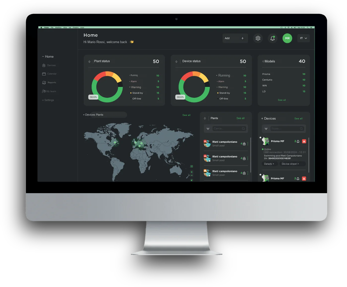
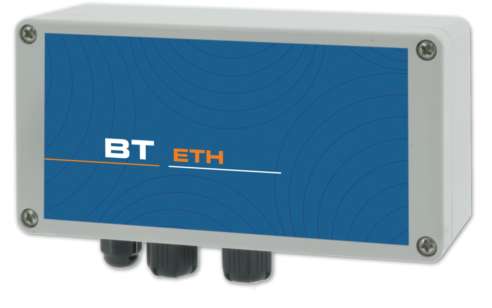
Connection to the web portal via network cable: measurements, set points, dosing and alarms accessible from PC, tablet and smartphone.
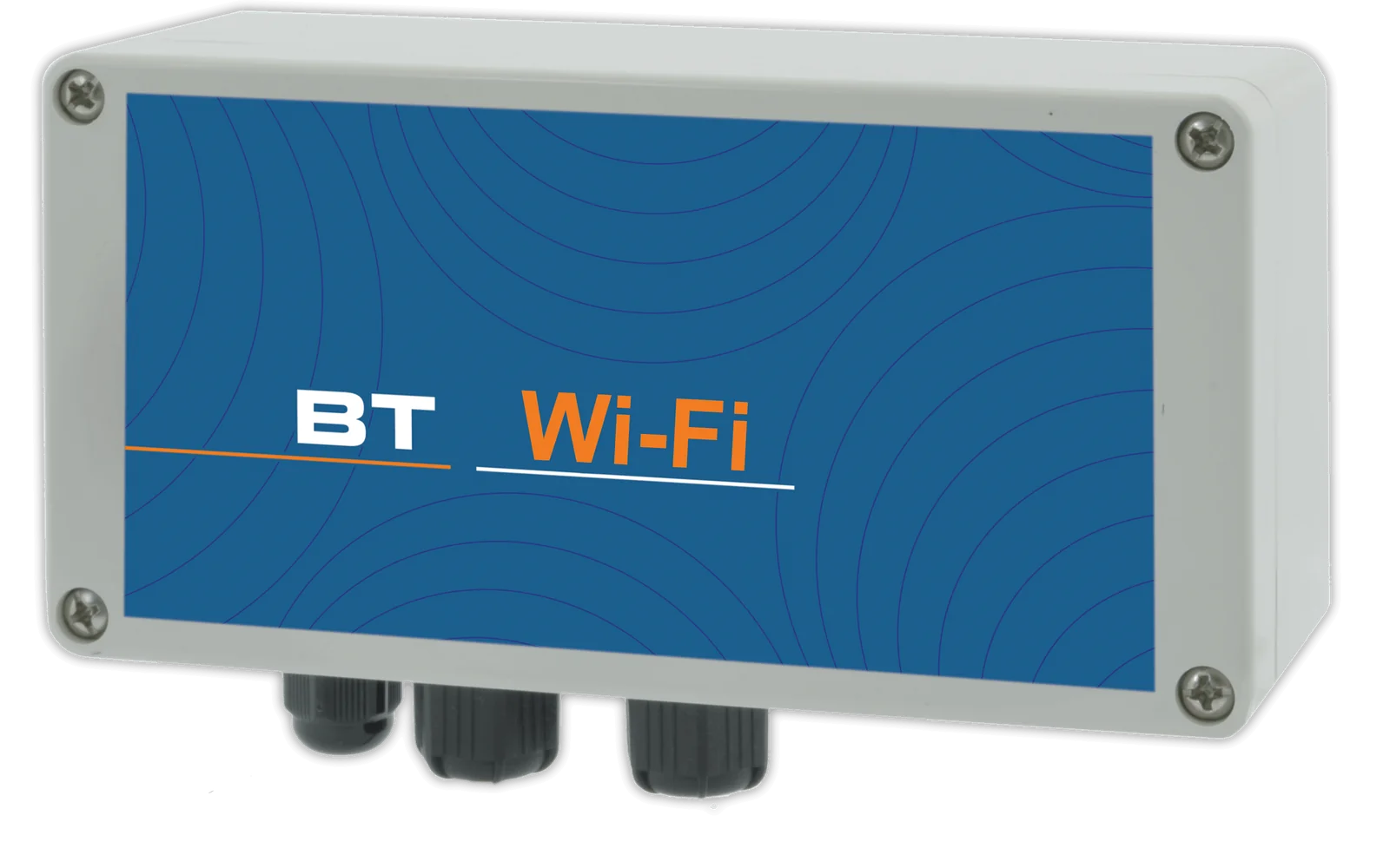
Wireless connection to the web portal, with the same functions as the cable connection.
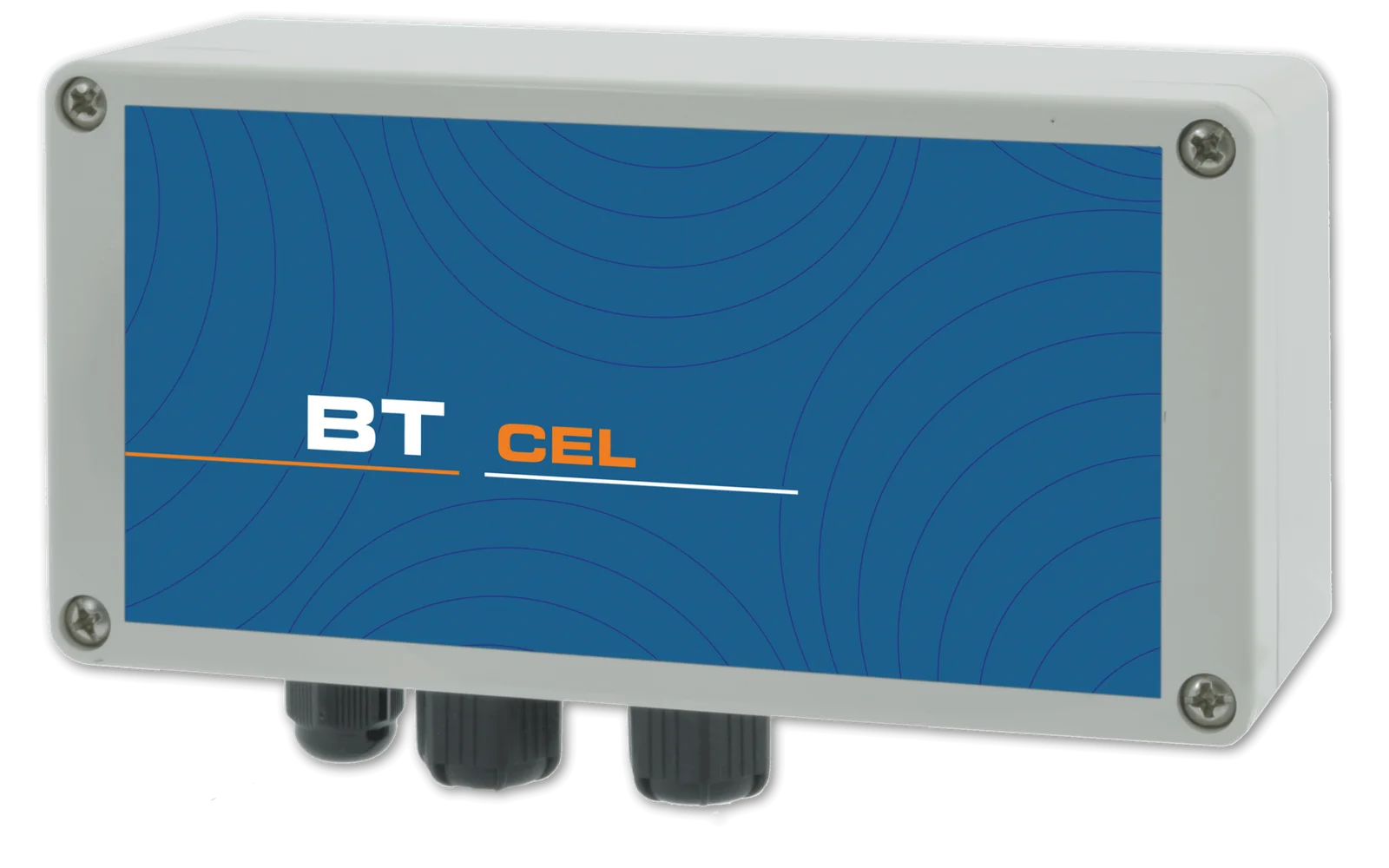
Connection via the cellular network for installations without a local network, with alarm notification by SMS or e-mail.
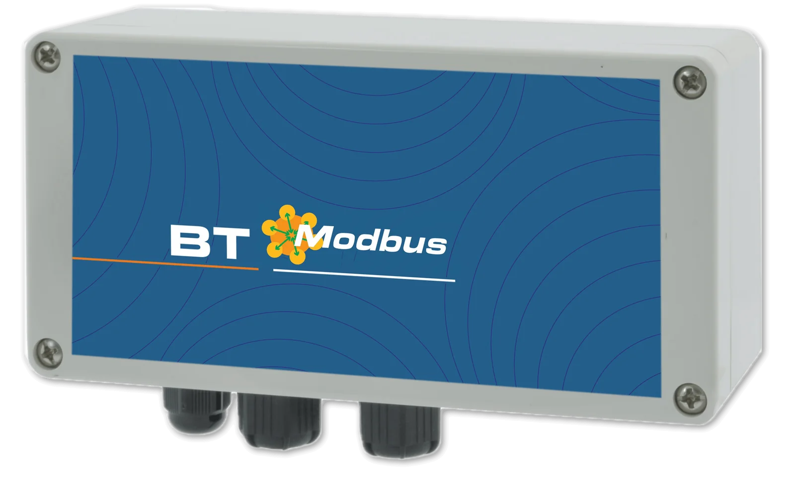
Integration into your PLC via serial port.

Current signal proportional to the measured value, for remote monitoring or for controlling pumps and other instrumentation.
One communication type at a time: Ethernet, Wi-Fi, 4G or Modbus RTU (built into the standard versions, optional on the PLUS versions). 4/20 mA outputs and meter input standard on the PLUS versions, optional on the standard versions.
A single account brings together all registered installations, each with its own devices: the web portal, free of charge and with no subscription, can be accessed from PC, Mac, tablet and smartphone and allows every parameter to be both viewed and changed, with an encrypted connection and protected access.

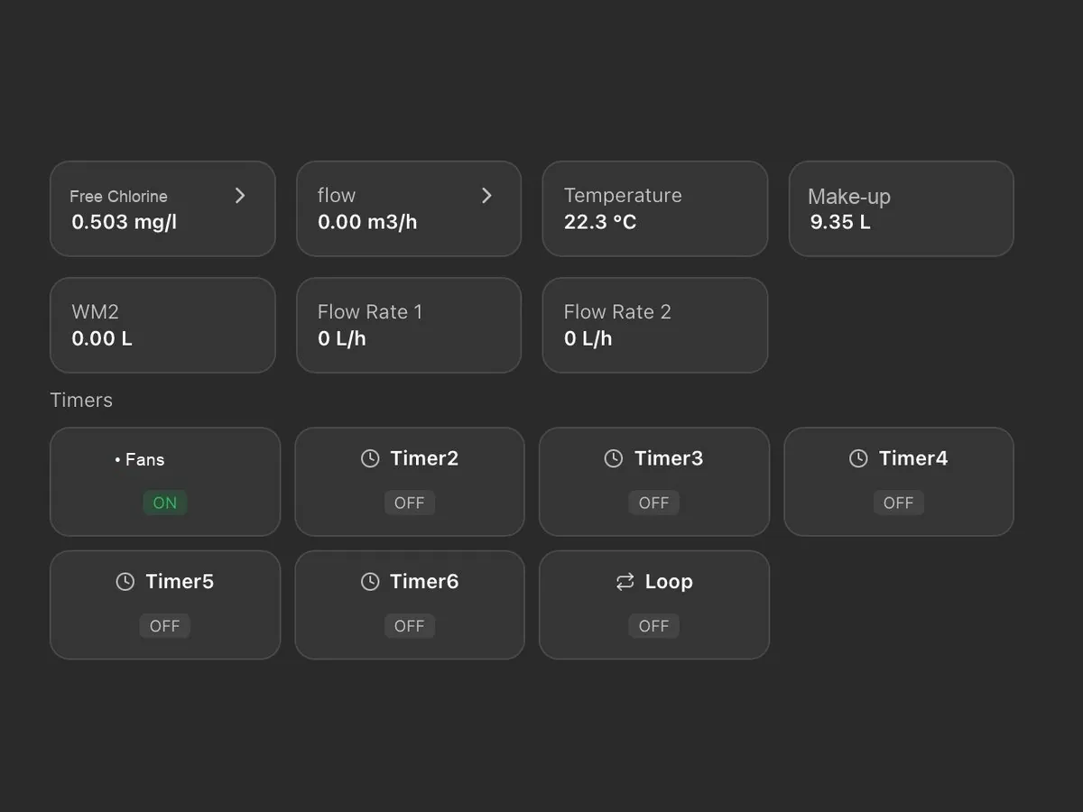
On a single screen: probe readings, chemical levels, pump activation thresholds and active alarms, with the status of installations and devices (normal, warning, alarm, standby, not connected).
Installations appear on an interactive map with their status and open with a click; for each one, the local weather conditions and temperature are also shown.
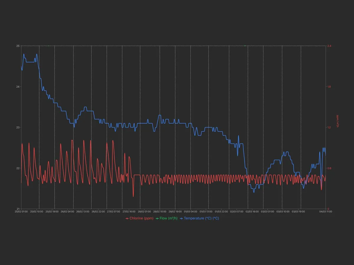
Archive of measurements and alarms, available for consultation at any time with charts and numerical reports exportable in Excel format.
Alarm thresholds for readings, dosing, faulty probe and out-of-range readings, with notification by e-mail or SMS depending on the communication system; a warning is also issued when an installation remains disconnected beyond the set time.
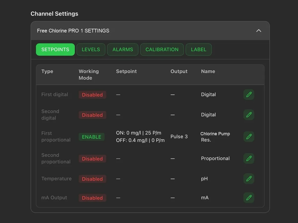
Remote modification of the set points, of the dosing pump activation thresholds and of the corresponding hourly flow rate.
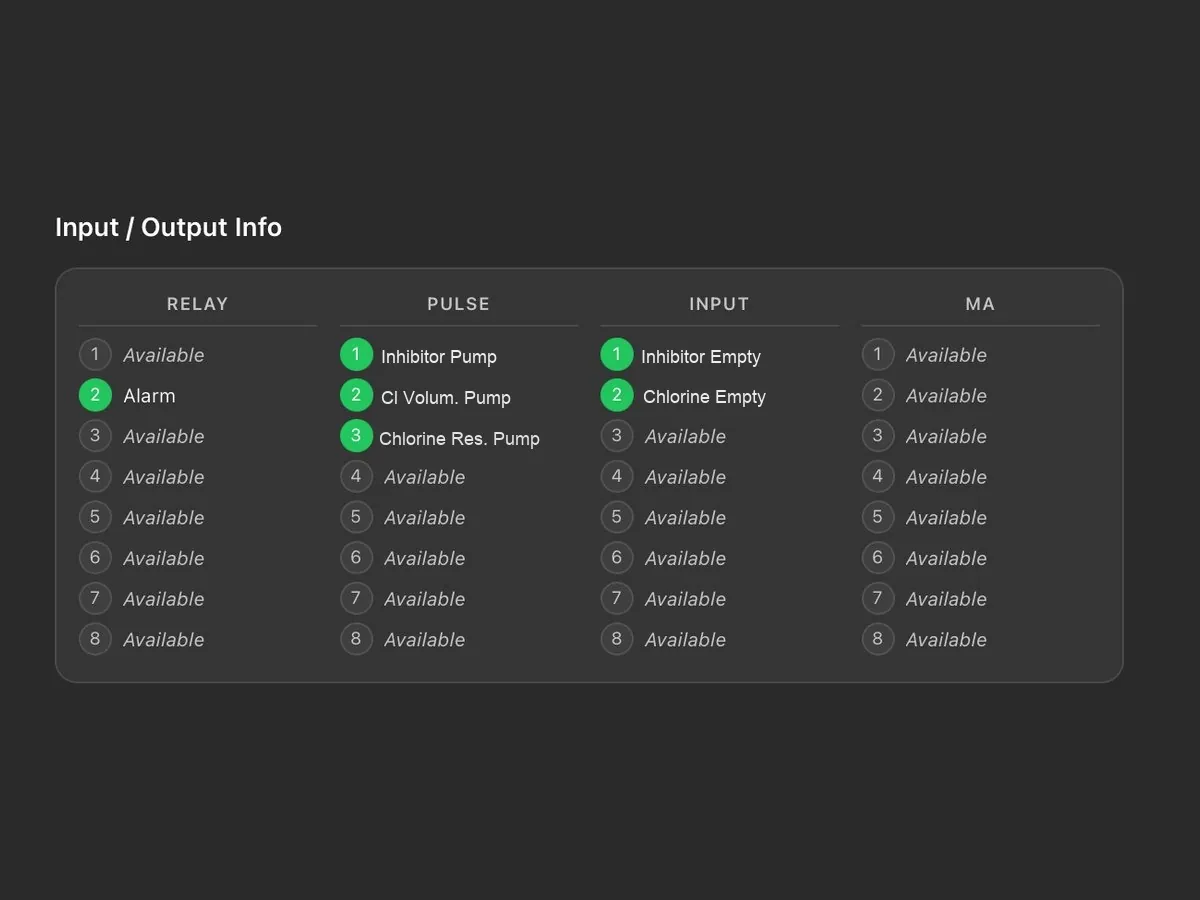
Status of relays, pulse outputs, digital inputs and current outputs, with the name assigned to each connection.
Tasks are scheduled by installation or by device and assigned to technicians; a reminder is sent by e-mail two days before the due date. Each task is shown as scheduled, due, overdue or completed.
The main account has full access and creates the technicians’ accounts, each enabled only for the assigned installations and devices; the last login and activity of each technician are visible.
Reports on devices, tasks and technicians, downloadable in PDF or CSV with the customer’s logo; the log keeps the history of operations and disconnections.
Logo, main colour and light or dark theme; the tiles on the main screen can be rearranged by dragging them. Two installations can be displayed side by side for comparison.
Each device is added through a guided procedure: the model is recognised automatically and associated with the installation, together with the technician to be contacted.
As an alternative to the portal, the Modbus RTU or TCP/IP port allows integration into the plant supervision system.
The requirements of the sector and the comparison with the other systems available.
Fertigation systems →Systems are supplied pre-assembled and tested, in the form best suited to the plant room: on a panel, in a cabinet or on a skid (with cover, in a box or on a frame), also tailor-made. Some examples.
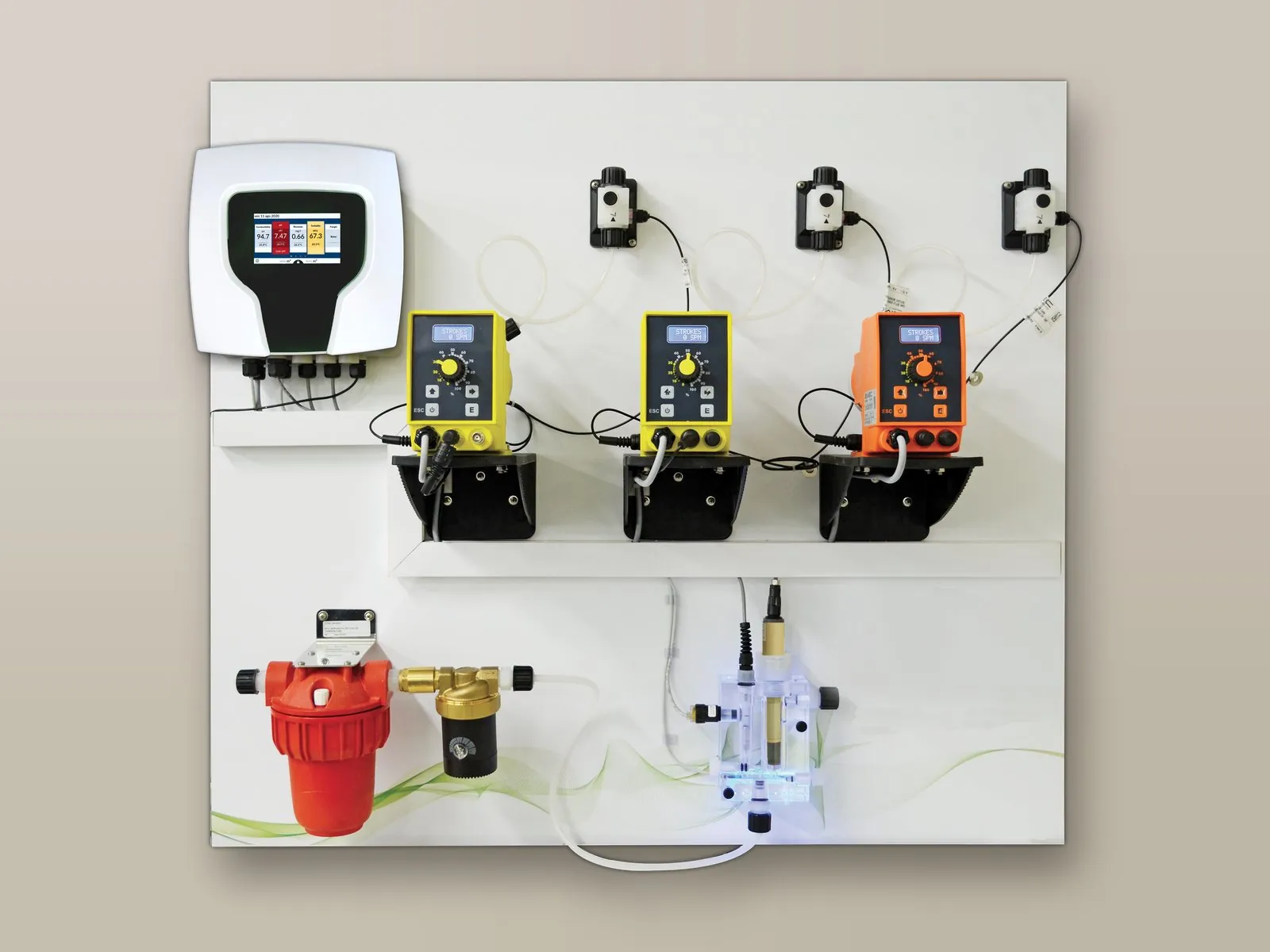
Controller, pumps, probe holder and accessories mounted and wired on a wall panel.
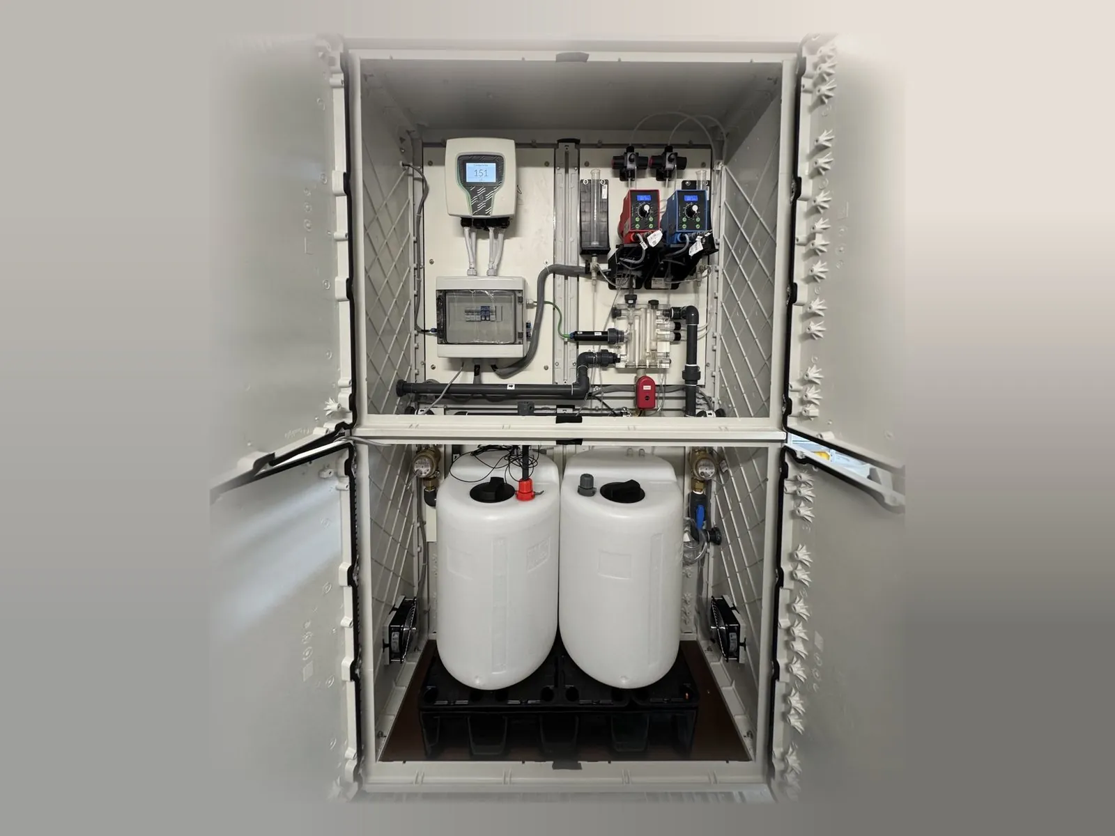
System panel and chemical tanks housed in a single cabinet.
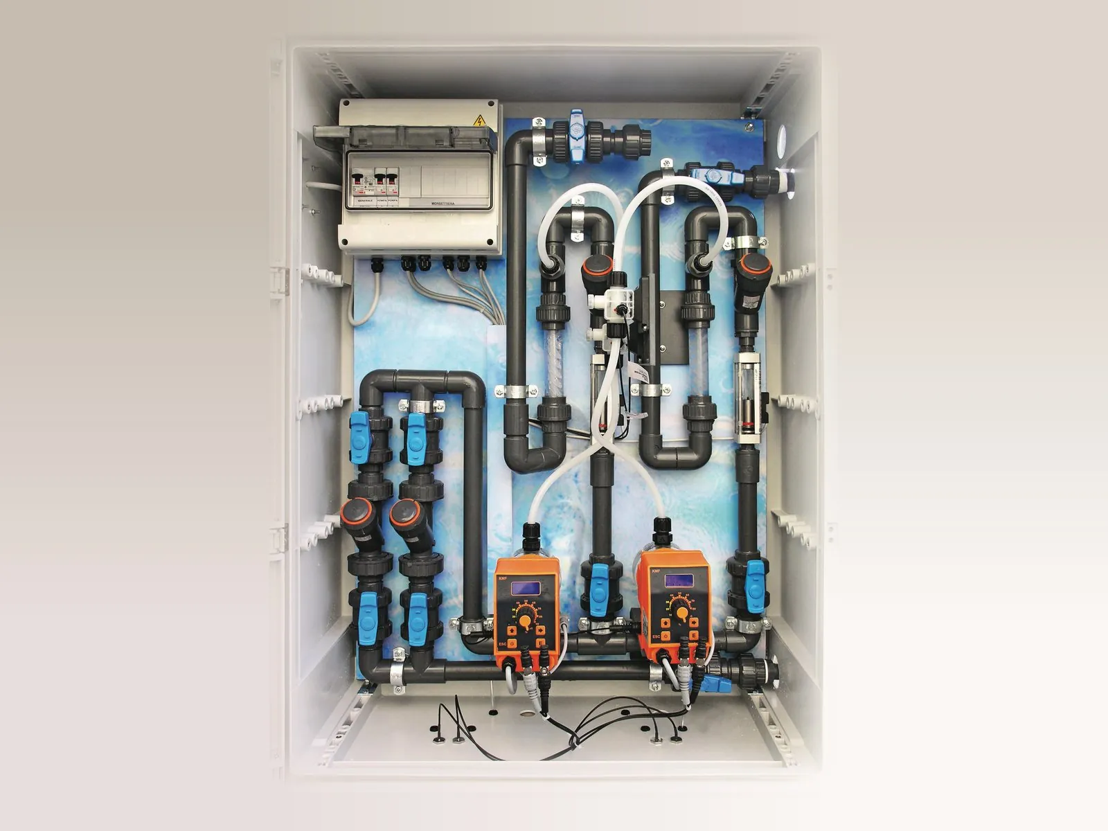
Pipework, pumps and electrical panel in a wall cabinet with door.
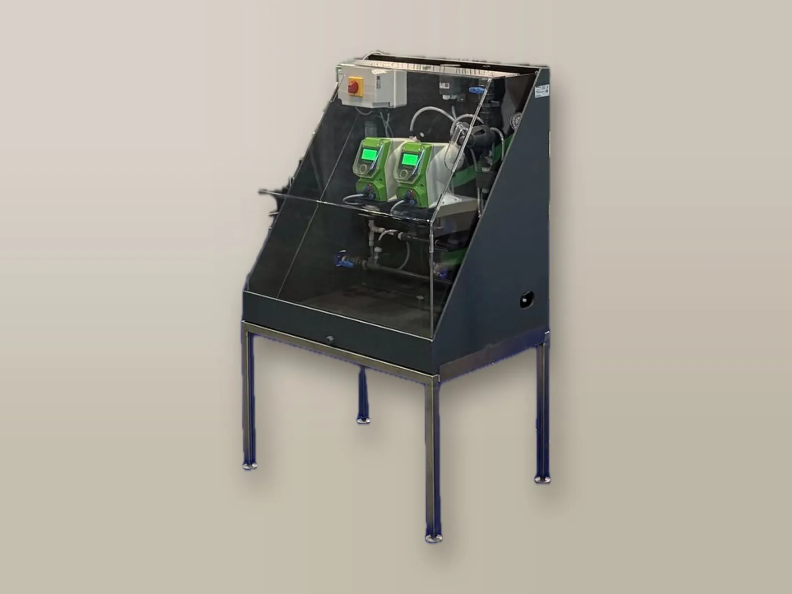
Skid with raised stainless steel frame and protective PMMA cover.
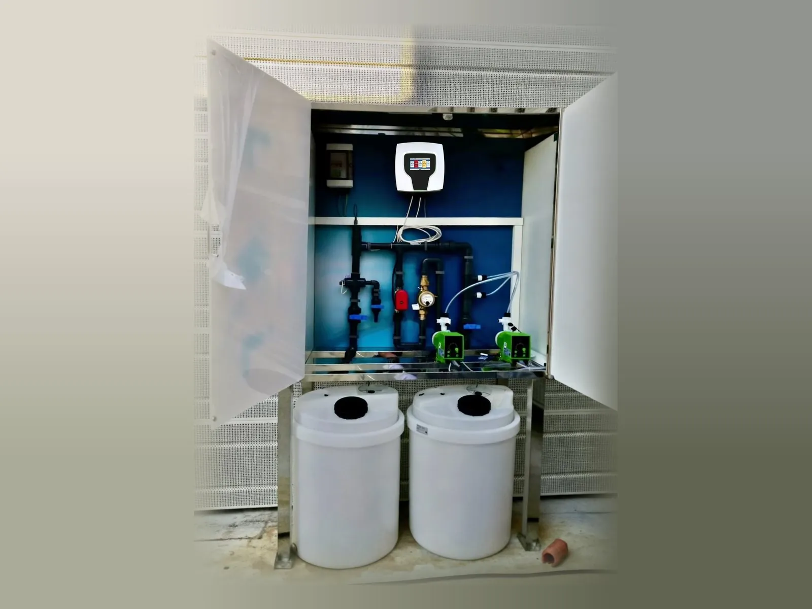
Skid enclosed in a box with door, with the chemical tanks at the base.
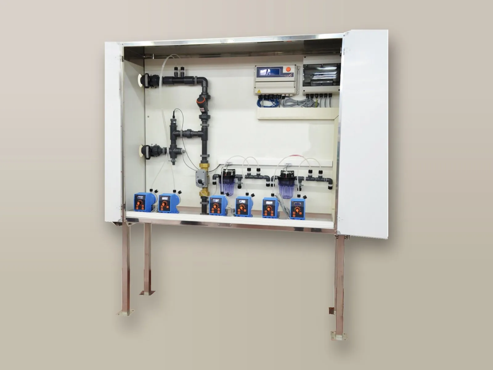
Skid on a frame with doors, pre-assembled and ready for connection.
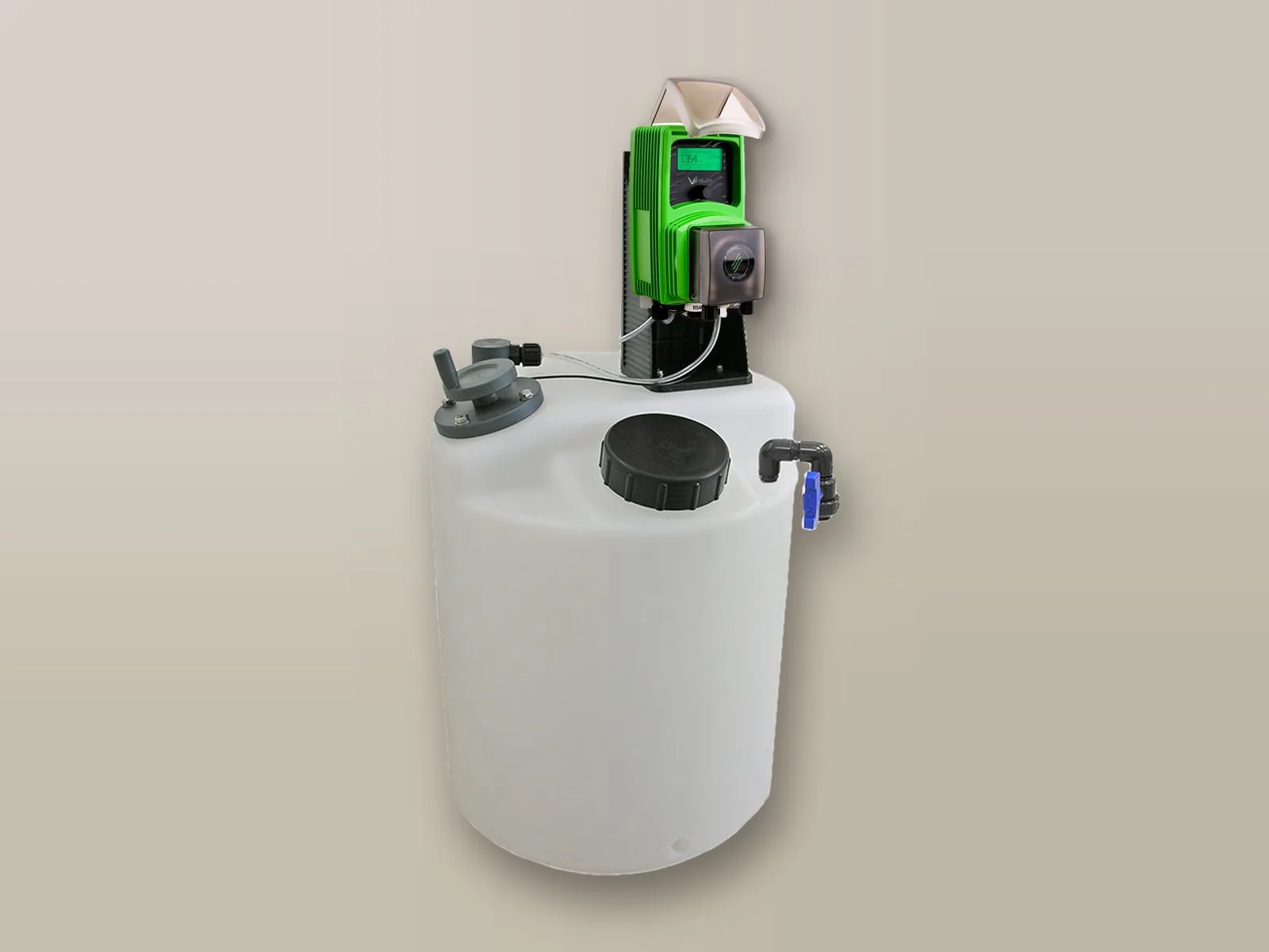
Dosing pump mounted directly on the tank: the most compact solution.
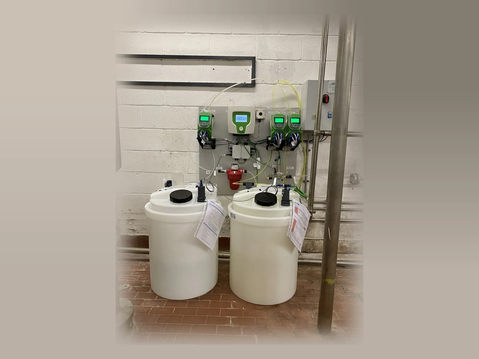
Wall installation in the plant room, with the chemical tanks on the floor.
Pumps, controllers or components supplied by the customer can also be fitted, with custom dimensions, back panel and electrical panel. Dosing stations and skids →
For pH control the basic solution is the dosing station; when dosing has to be controlled by the measured value, measuring controllers are used.
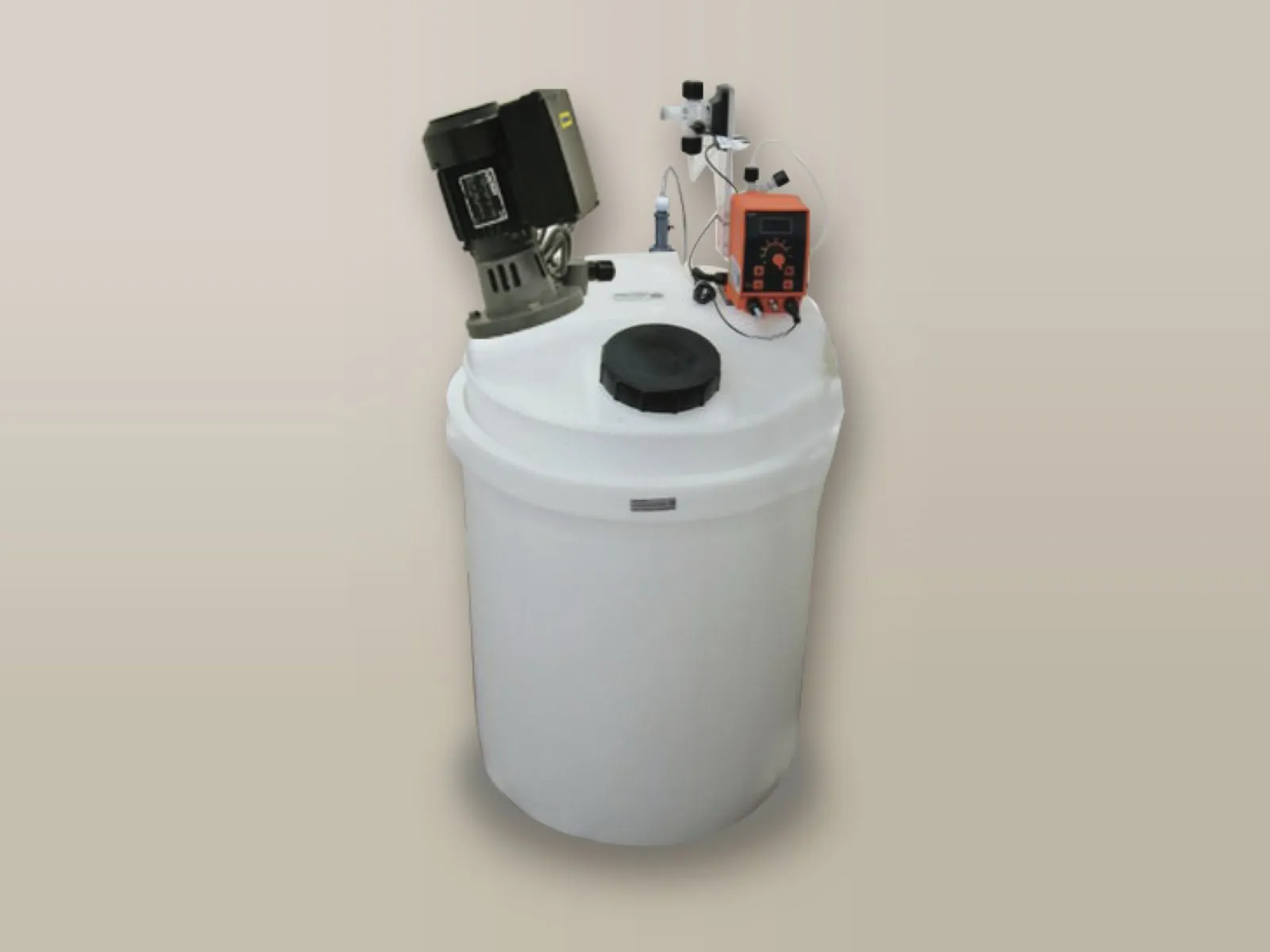
The simplest solution: the pump doses at a constant rate or in proportion to the volume of water measured by the pulse-output water meter.
Details →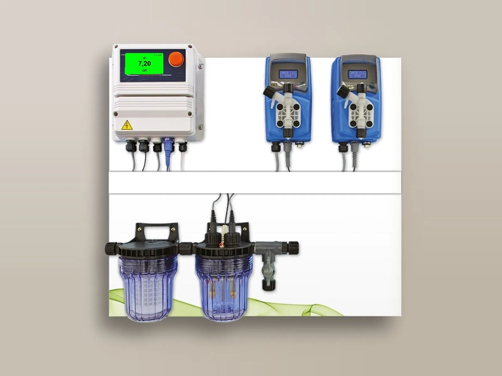
pH measurement and dosing of acid or alkali up to the set value.
Details →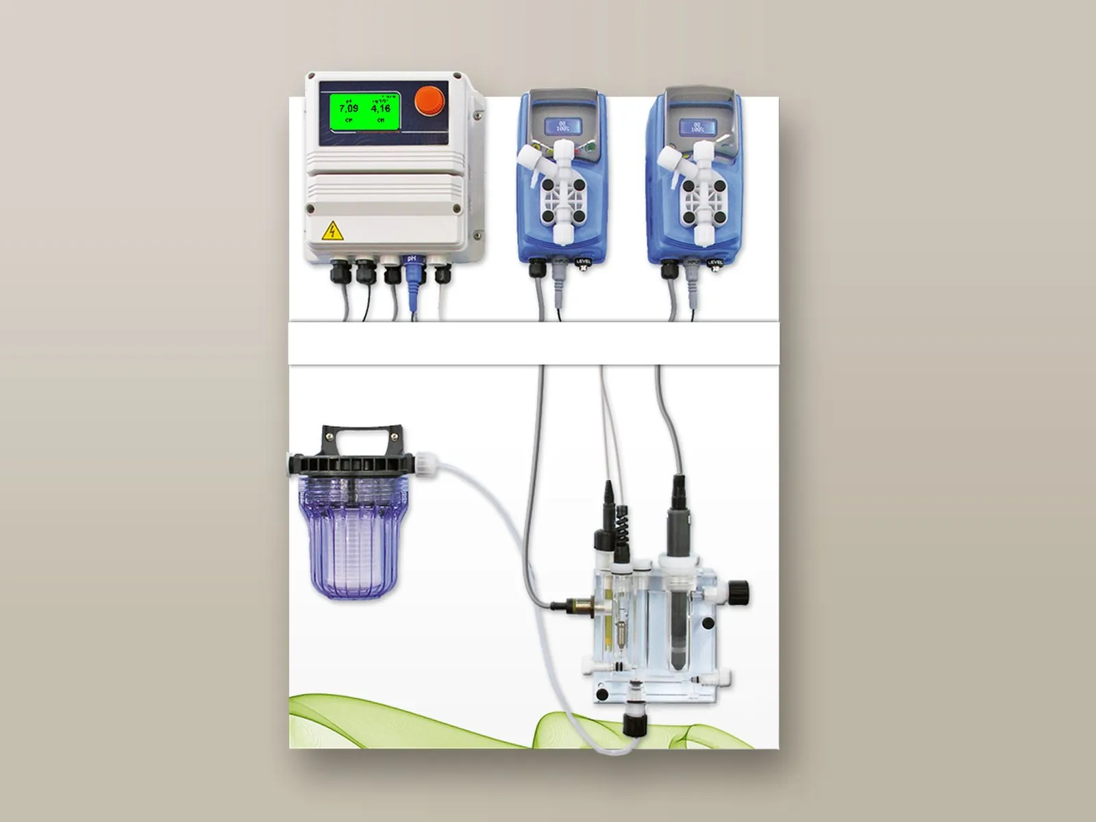
Simultaneous management of two parameters, for example pH and chlorine, with a single controller.
Details → Management of up to 10 parameters and of all the pumps in the installation, with touch screen and remote control as standard.
Details →Describe your plant and the flow rate of water to be treated: we will size the controller, pumps and accessories.
Call or write to us: a technician will reply with a tailored proposal of controllers, pumps, probes and accessories.