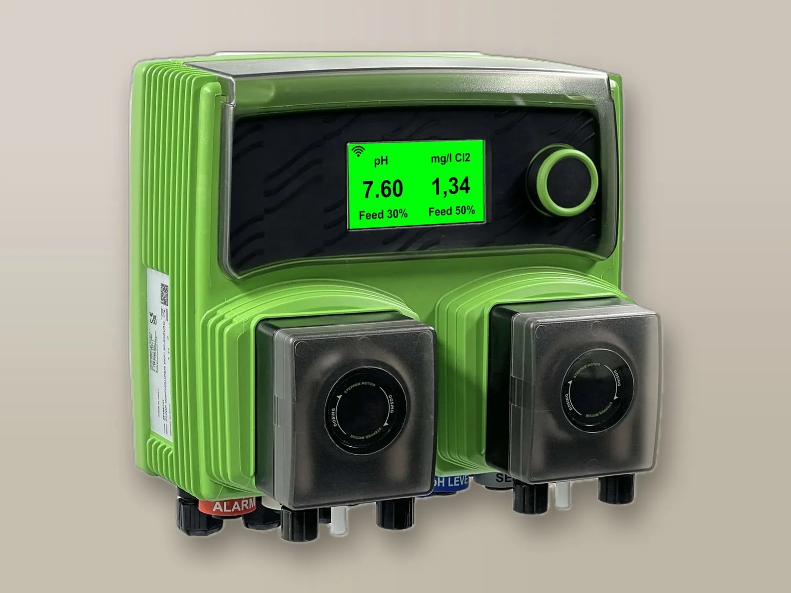
WNpHCl Chlorine
With integrated pH and free chlorine measuring controllers.
- Proportional to pH
- Proportional to free chlorine (open amperometric cell)
- Proportional to free chlorine (closed amperometric cell)
Stepper motor peristaltic dosing pumps for swimming pools: they simultaneously dose the pH corrector and the disinfectant (sodium hypochlorite, bromine or hydrogen peroxide), with integrated measuring controllers. Peristaltic operation is silent and the stepper motor ensures high dosing precision.
The choice of model depends on the disinfectant used and on the measuring controller required.
With integrated pH and free chlorine measuring controllers.
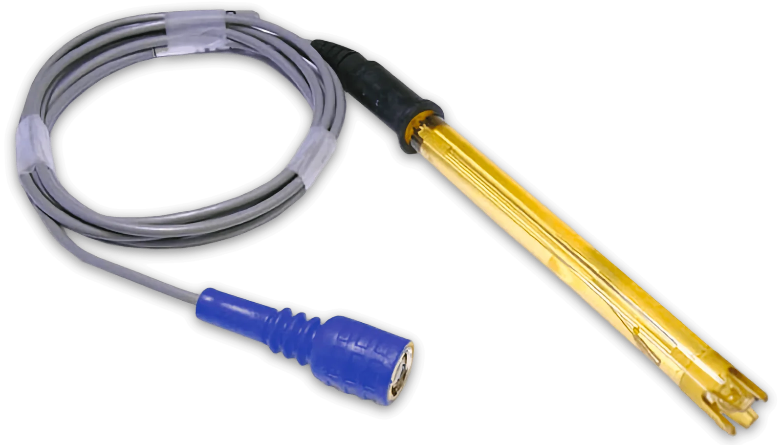 EpHSpH electrode
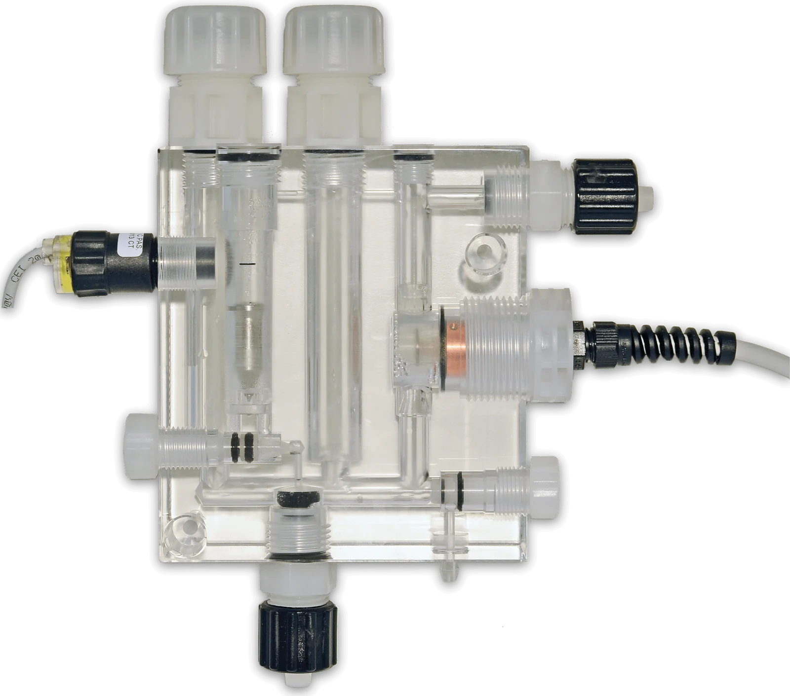 ECL6Open amperometric cell for free chlorine
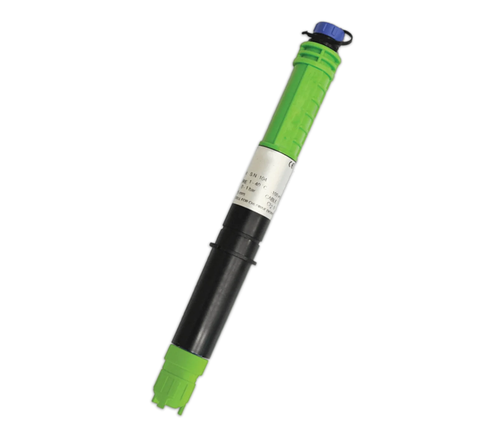 SCL 3S/20Closed (membrane) amperometric cell for free chlorine
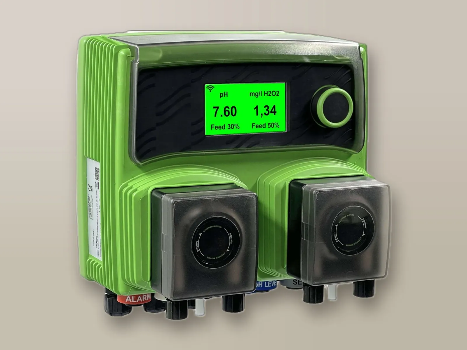
With integrated pH and hydrogen peroxide measuring controllers.
EpHSpH electrode
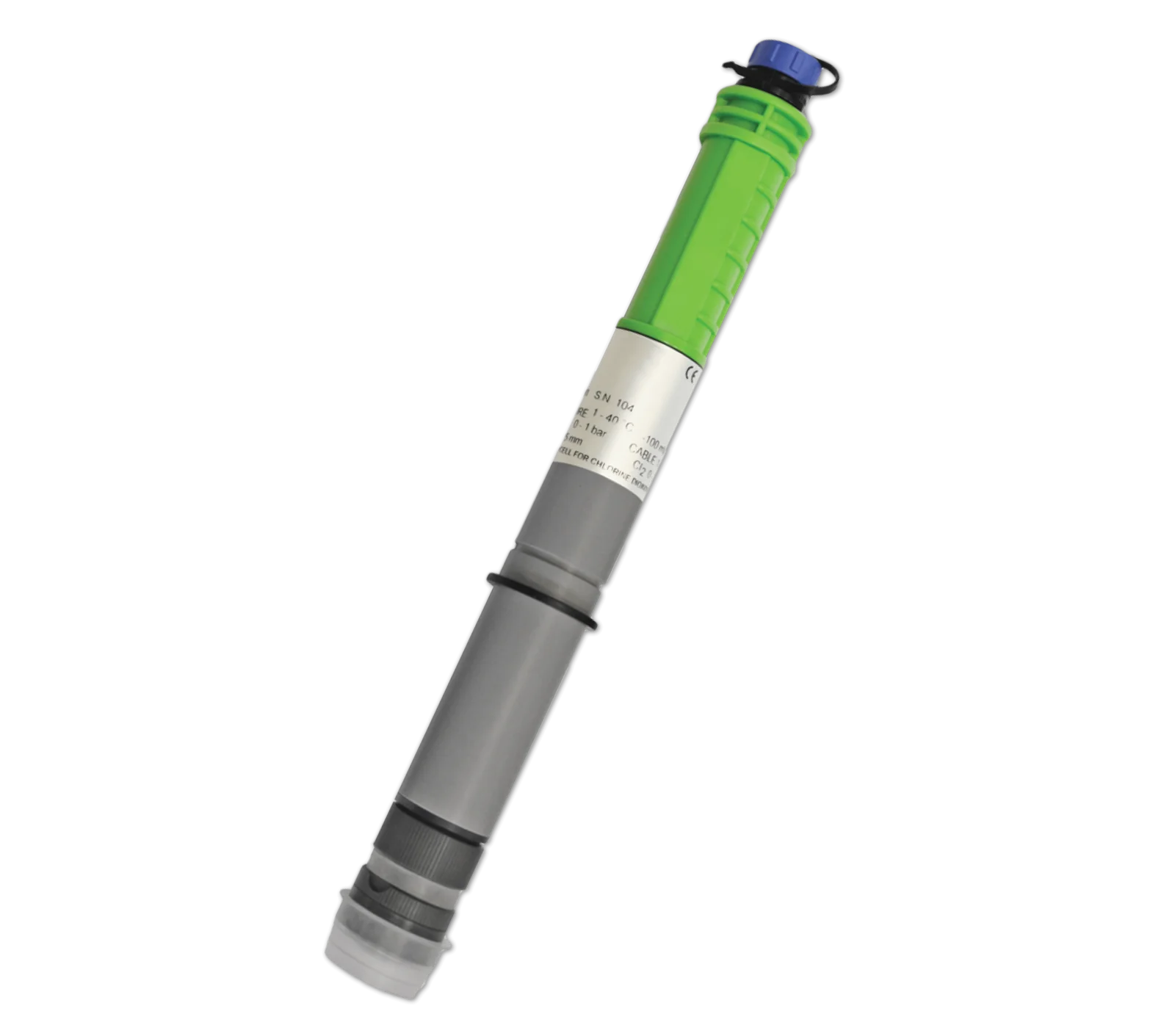 SCL 9/200Closed (membrane) amperometric cell for free hydrogen peroxide
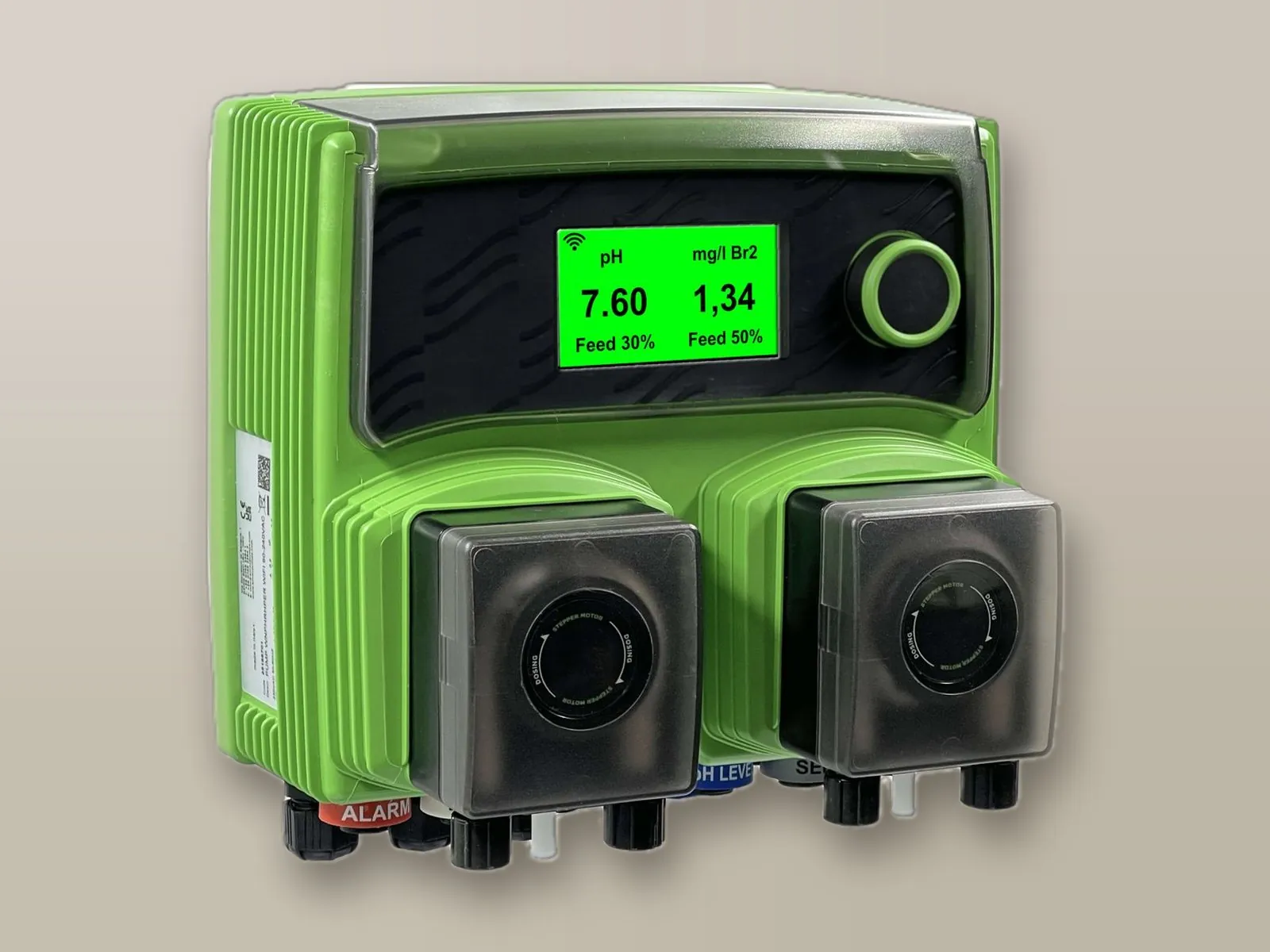
With integrated pH and bromine measuring controllers.
EpHSpH electrode
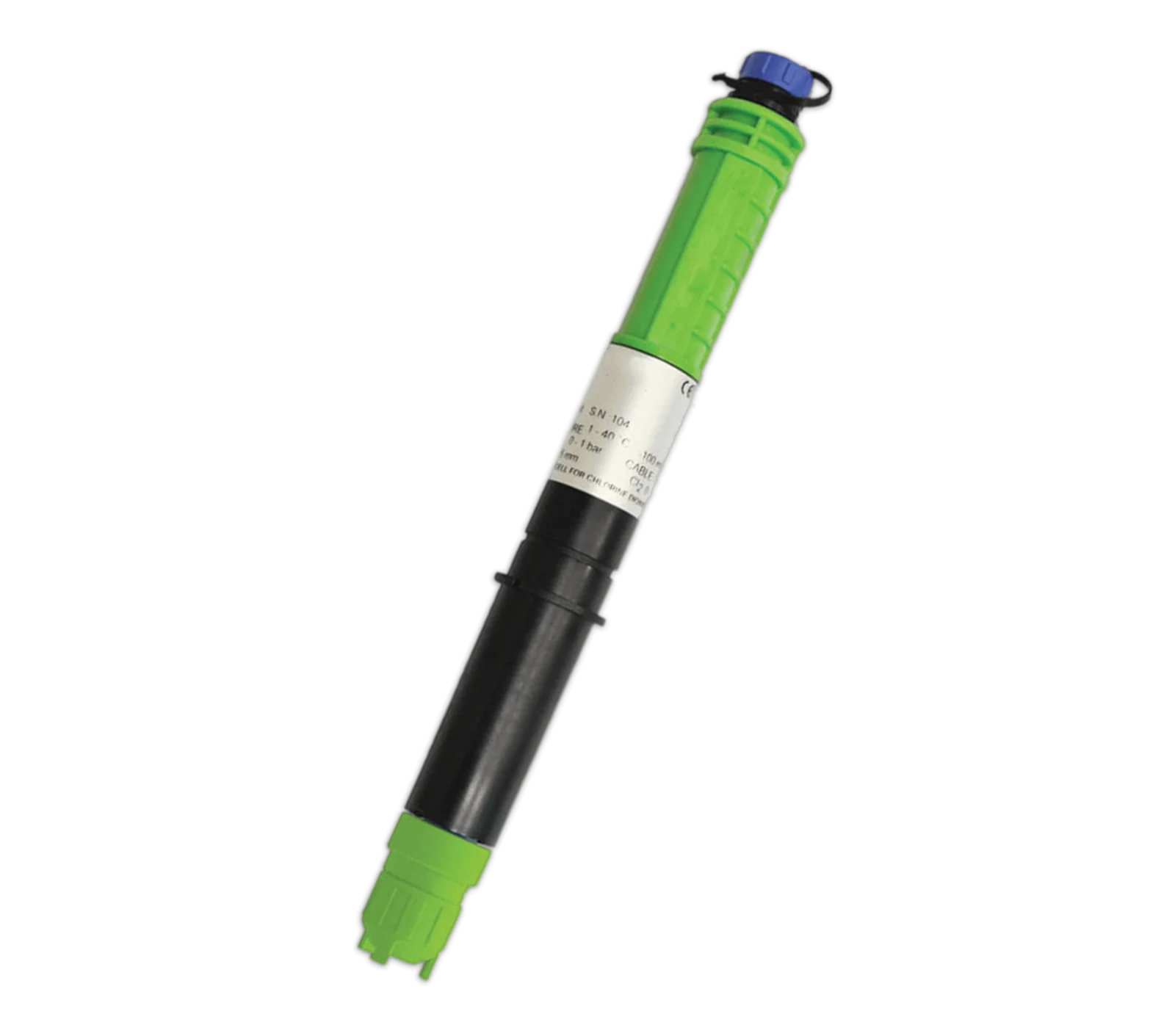 SBRClosed (membrane) amperometric cell for free bromine
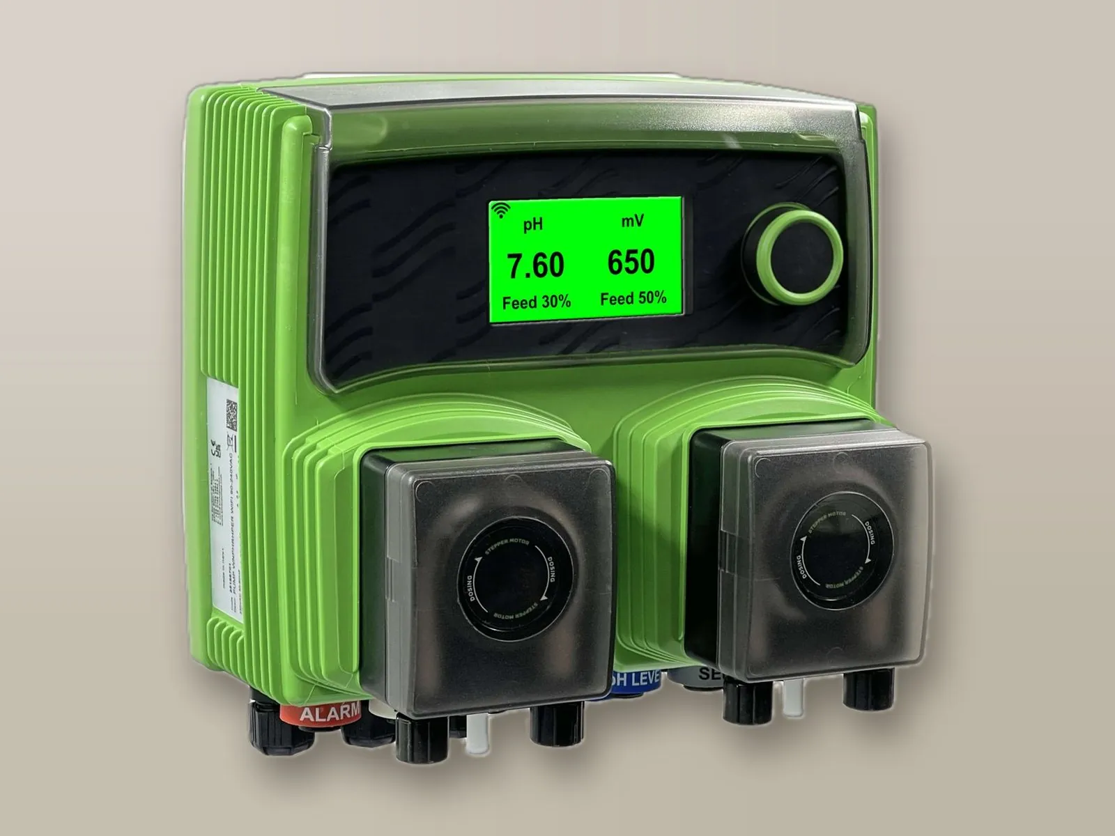
With integrated pH and Redox (ORP) measuring controllers.
EpHSpH electrode
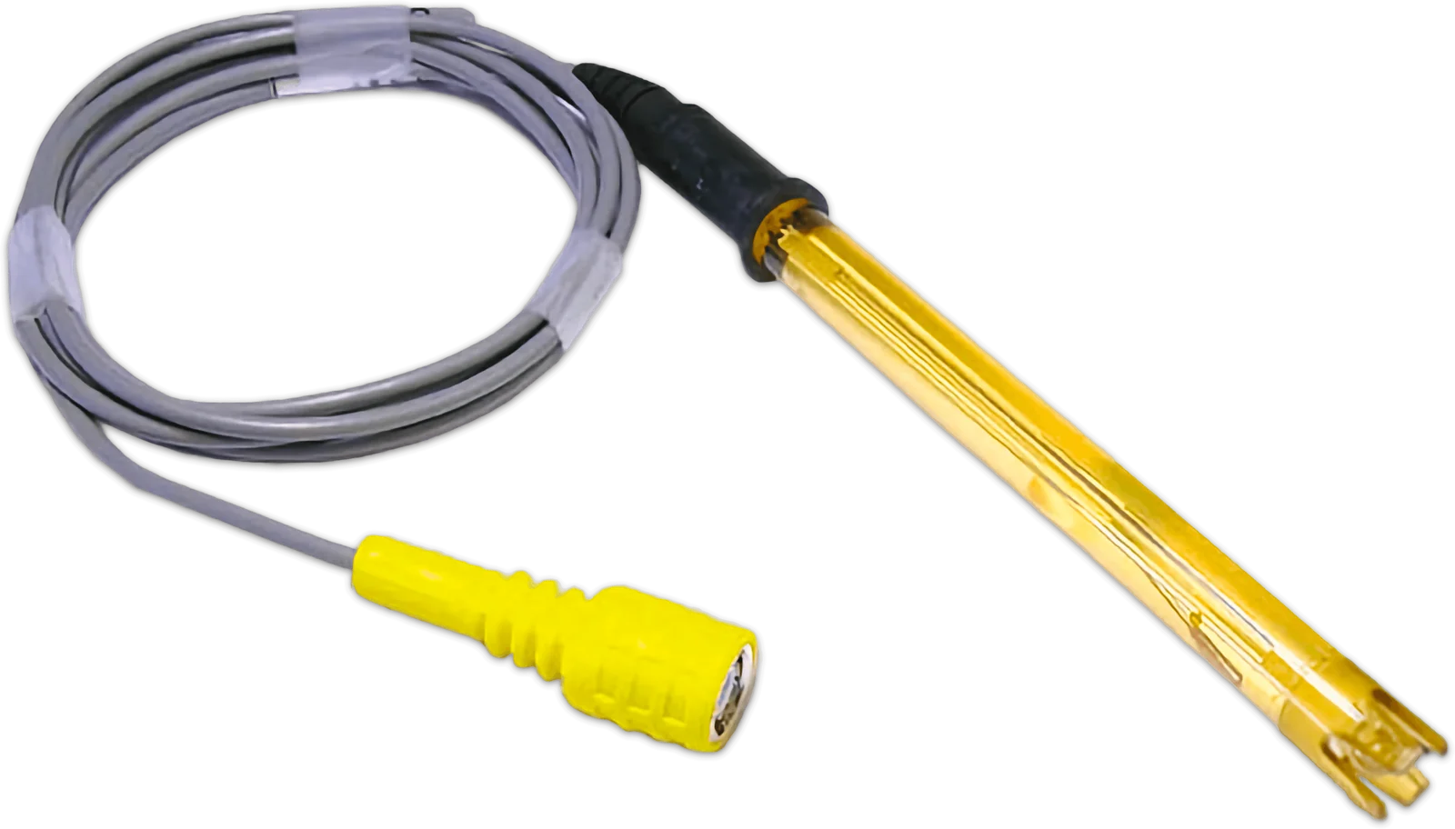 ERhSRedox (ORP) electrode
| Function | pHCl | pHCl Per. | pHCl Br. | pHRh |
|---|---|---|---|---|
| Dosing modes | ||||
| Proportional to pH | ● | ● | ● | ● |
| Proportional to Redox | – | – | – | ● |
| Proportional to free chlorine (open amperometric cell) | ● | – | – | – |
| Proportional to free chlorine (closed amperometric cell) | ● | – | – | – |
| Proportional to free bromine | – | – | ● | – |
| Proportional to hydrogen peroxide | – | ● | – | – |
| Functions | ||||
| Independent adjustment | ● | ● | ● | ● |
| Separate set points | ● | ● | ● | ● |
| Dosing priority | ● | ● | ● | ● |
| Level control (two tanks) | ● | ● | ● | ● |
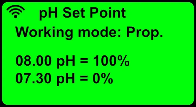
The required pH value (SET POINT) is set: the pump measures the pH by means of a pH electrode and progressively reduces the injection frequency as the set value approaches, stopping when the SET POINT is reached.
Models: WNpHCl Chlorine, WNpHCl Peroxide, WNpHCl Bromine, WNpHRh
The required Redox potential (ORP) (SET POINT) is set: the pump measures it by means of a Redox electrode and progressively reduces the injection frequency as the set value approaches, stopping when the SET POINT is reached.
Models: WNpHRh
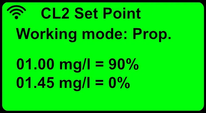
The required free chlorine concentration in mg/l (SET POINT) is set: the pump measures it by means of an open amperometric cell and progressively reduces the injection frequency as the set value approaches, stopping when the SET POINT is reached.
Models: WNpHCl Chlorine
The required free chlorine concentration in mg/l (SET POINT) is set: the pump measures it by means of a closed (membrane) amperometric cell and doses until the SET POINT is reached.
Models: WNpHCl Chlorine
The required free bromine concentration in mg/l (SET POINT) is set: the pump measures it by means of a closed amperometric cell for bromine and doses until the SET POINT is reached.
Models: WNpHCl Bromine
The required concentration of free hydrogen peroxide in mg/l (SET POINT) is set: the pump measures it by means of a closed amperometric cell for peroxide and doses until the SET POINT is reached.
Models: WNpHCl Peroxide
The flow rate is adjusted electronically by frequency, by varying the number of revolutions per minute of the motor. The exclusive AUTO DOSING function automatically configures system operation on the basis of the pool water volume.

The stepper motor and the control software deliver the product optimally with completely silent operation, a feature appreciated when dosing pH regulator and disinfectant in swimming pools and hot tubs.
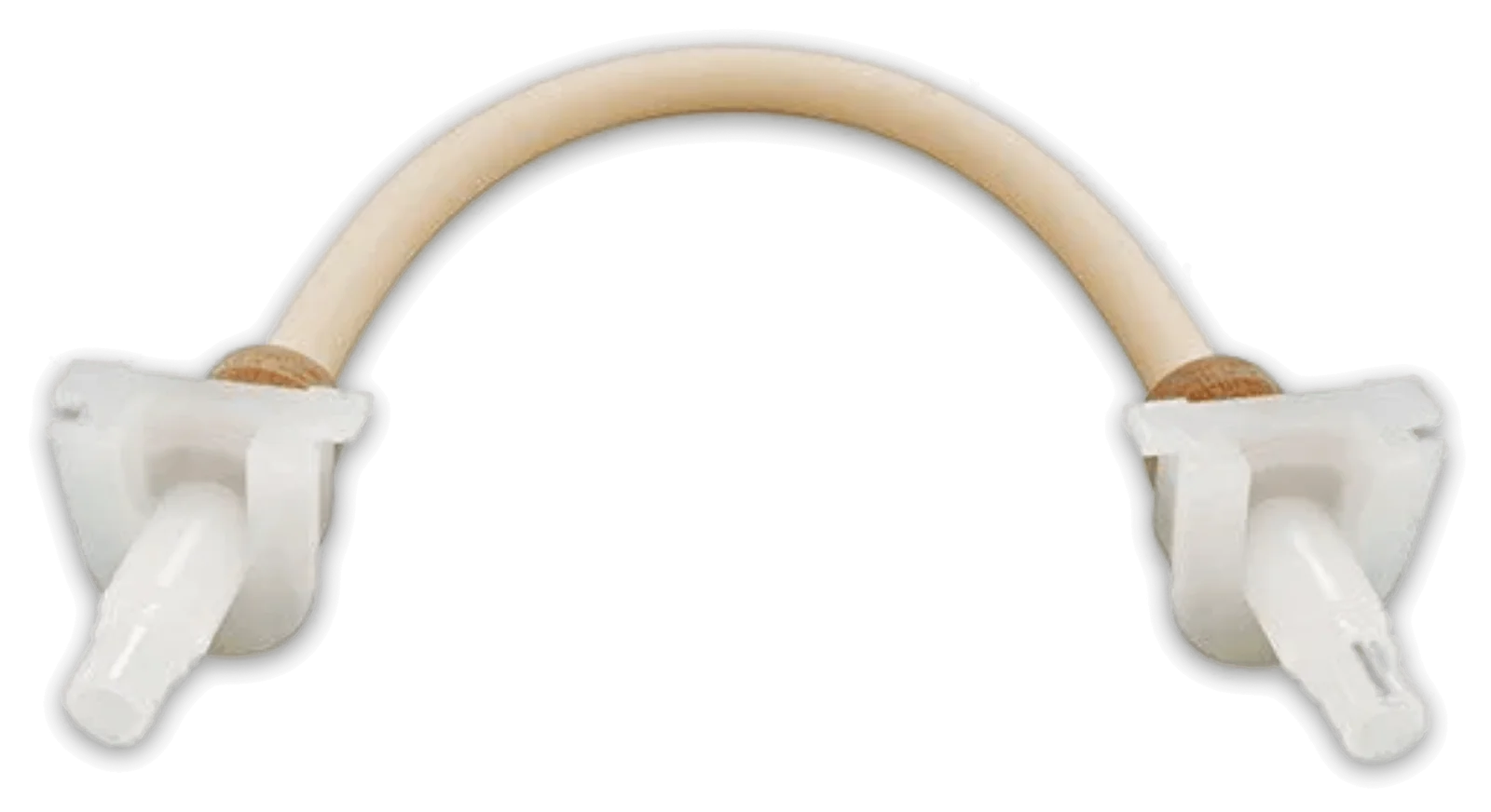
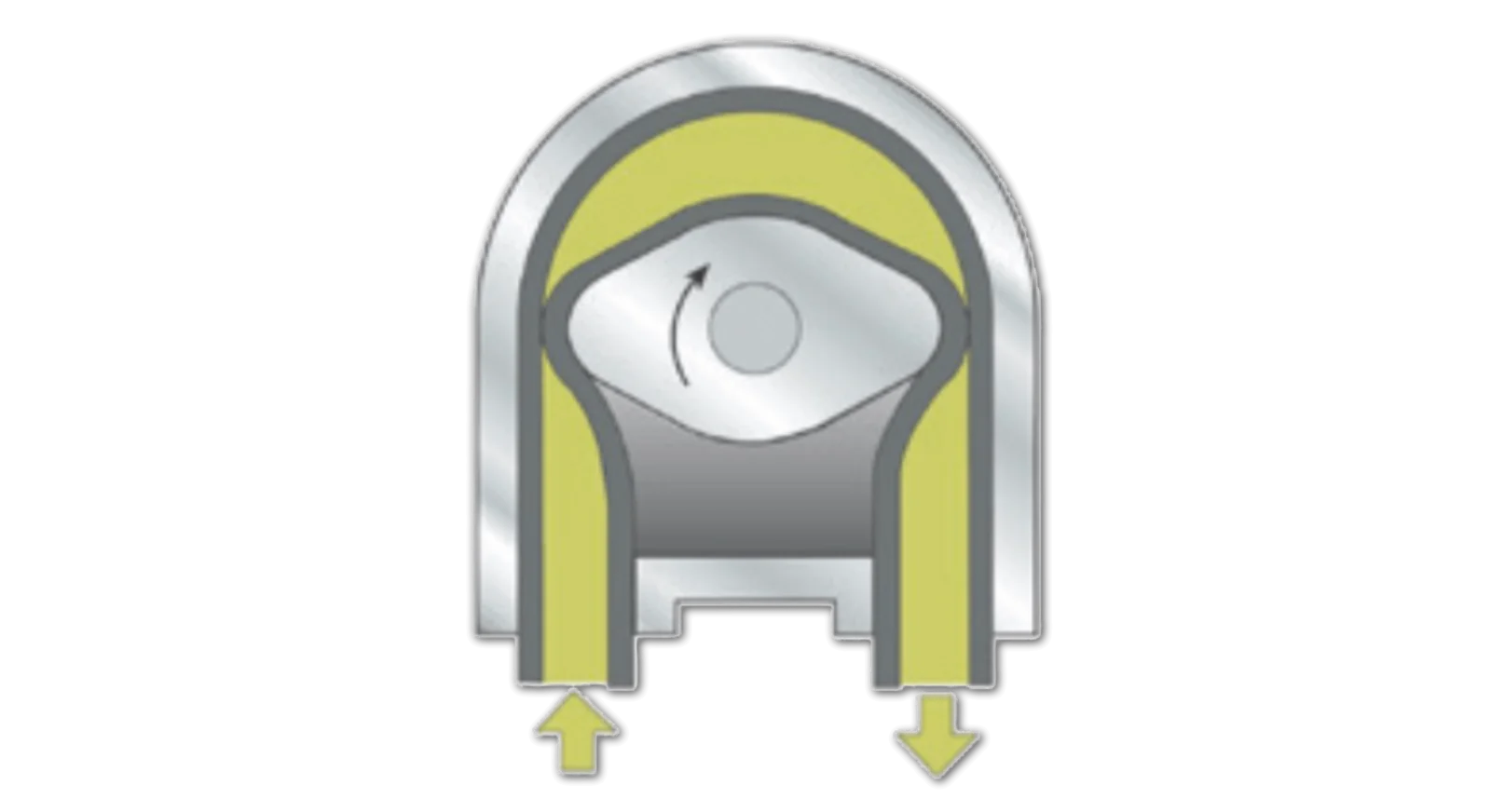
The tube is made of TPV, an elastomer compatible with most chemicals, which retains its elastic properties even after millions of compression cycles by the rollers.
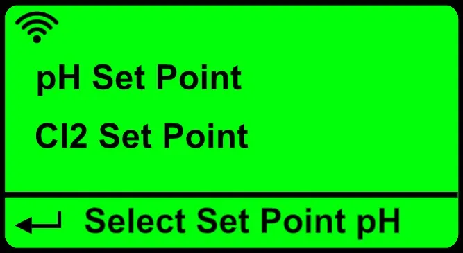
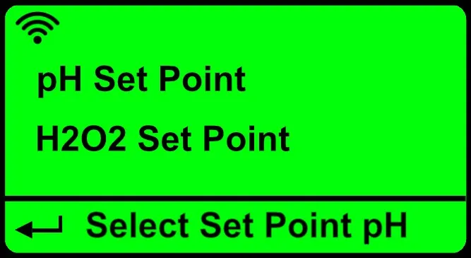
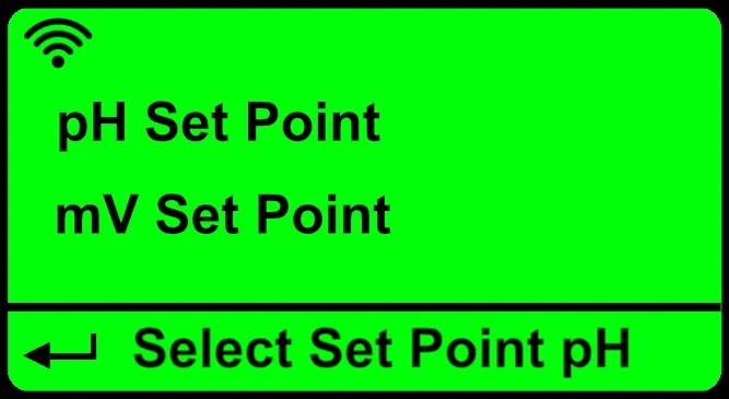
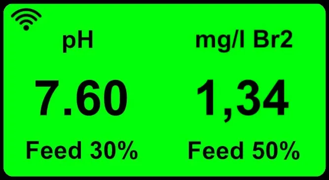
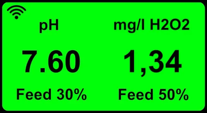
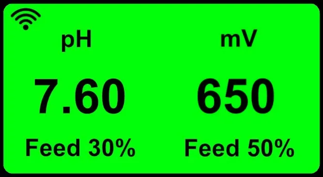
The display colour changes according to the operating status, so that an alarm can be recognised even from a distance. Below are the setting screens and the displays of all models.
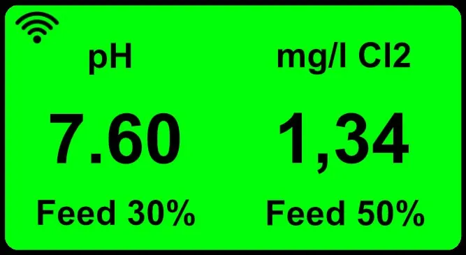
Normal operation according to the set parameters, no active alarms.
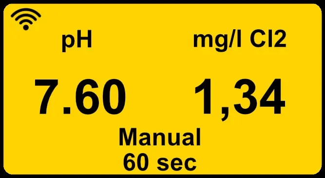
Non-blocking alarm, for example waiting for an external signal.
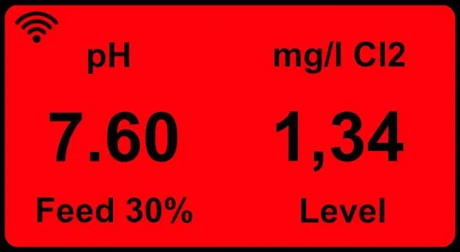
Blocking alarm, for example the chemical in the tank running out.
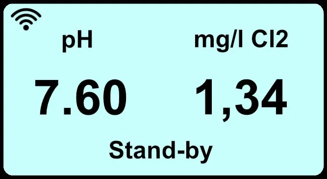
Pump stopped by an external control signal (stand-by).
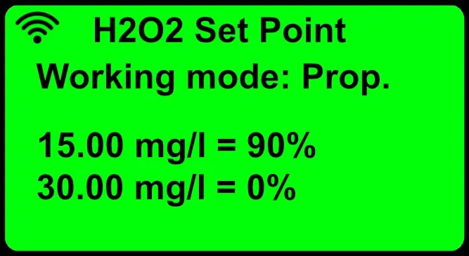
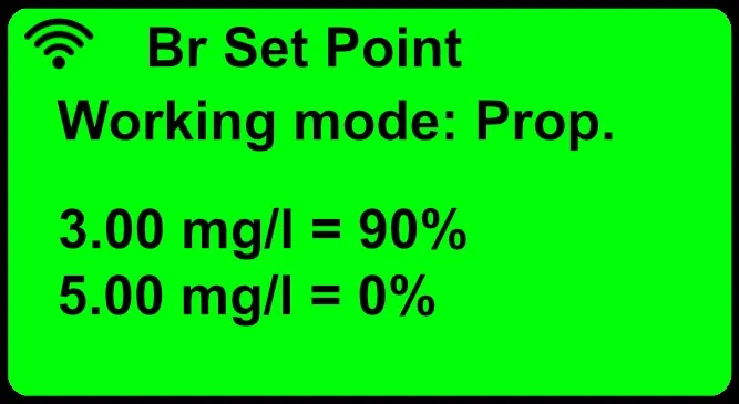
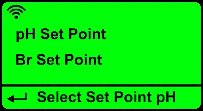
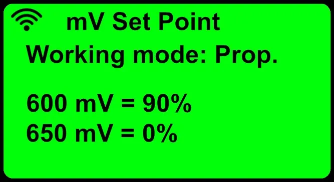
The WN pumps support two-way remote control: from the cloud portal, via Wi-Fi, Ethernet or cellular network, settings can be changed, operation can be checked and alarms can be received, such as product depletion; alternatively, the pumps can be integrated into a PLC via Modbus RTU.
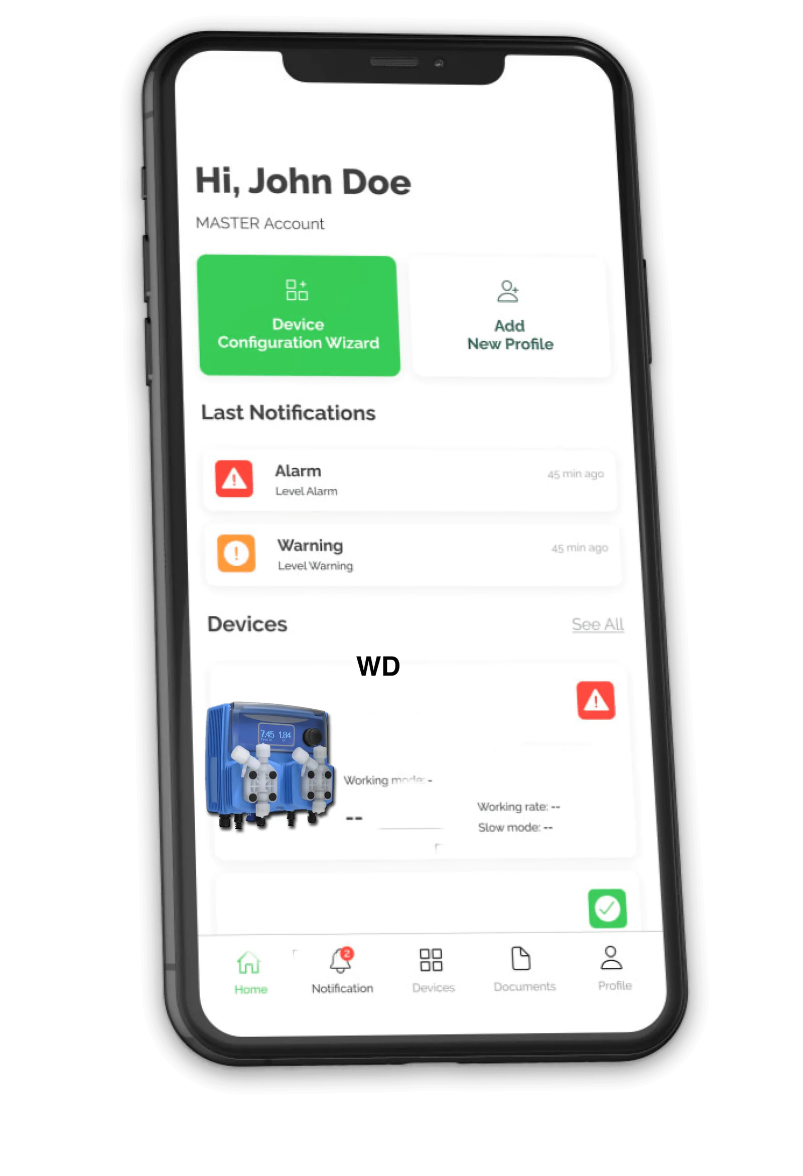
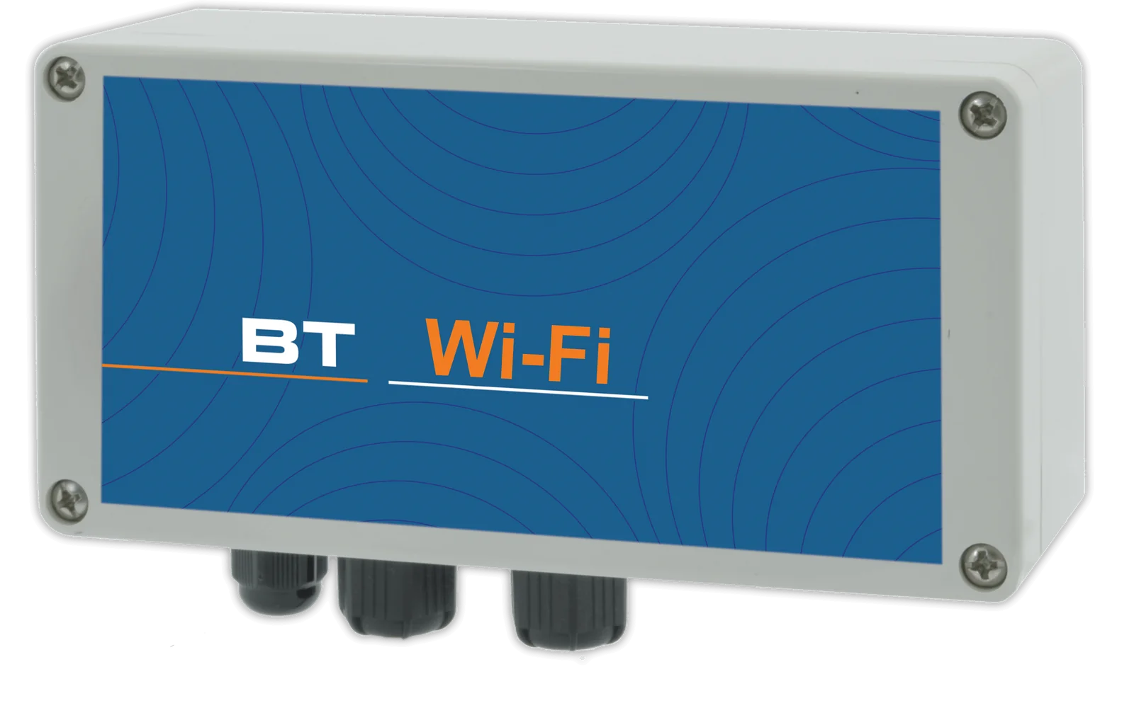
Allows connection to the Nimbus cloud portal to change settings, check operation and receive alarms, such as the chemical running out.

Pump programming directly from a smartphone.
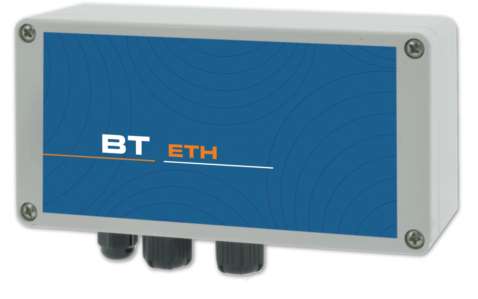
Allows connection to the Nimbus cloud portal via network cable to change settings, check operation and receive alarms.
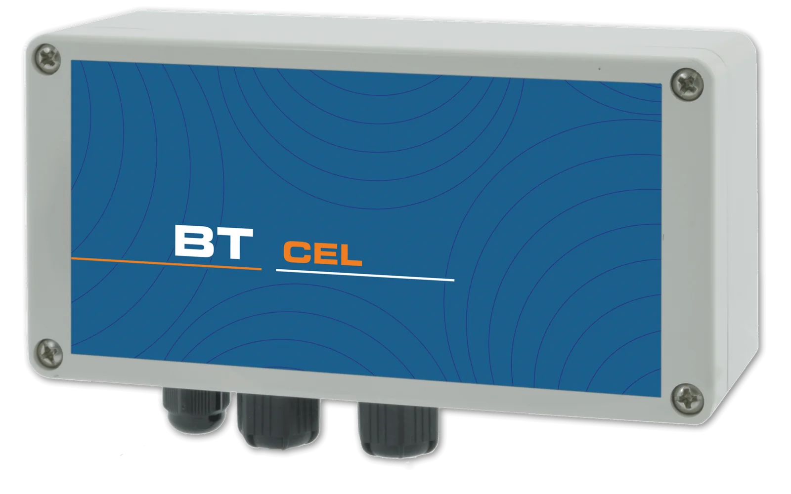
Allows connection to the Nimbus cloud portal via the cellular network to change settings, check operation and receive alarms.
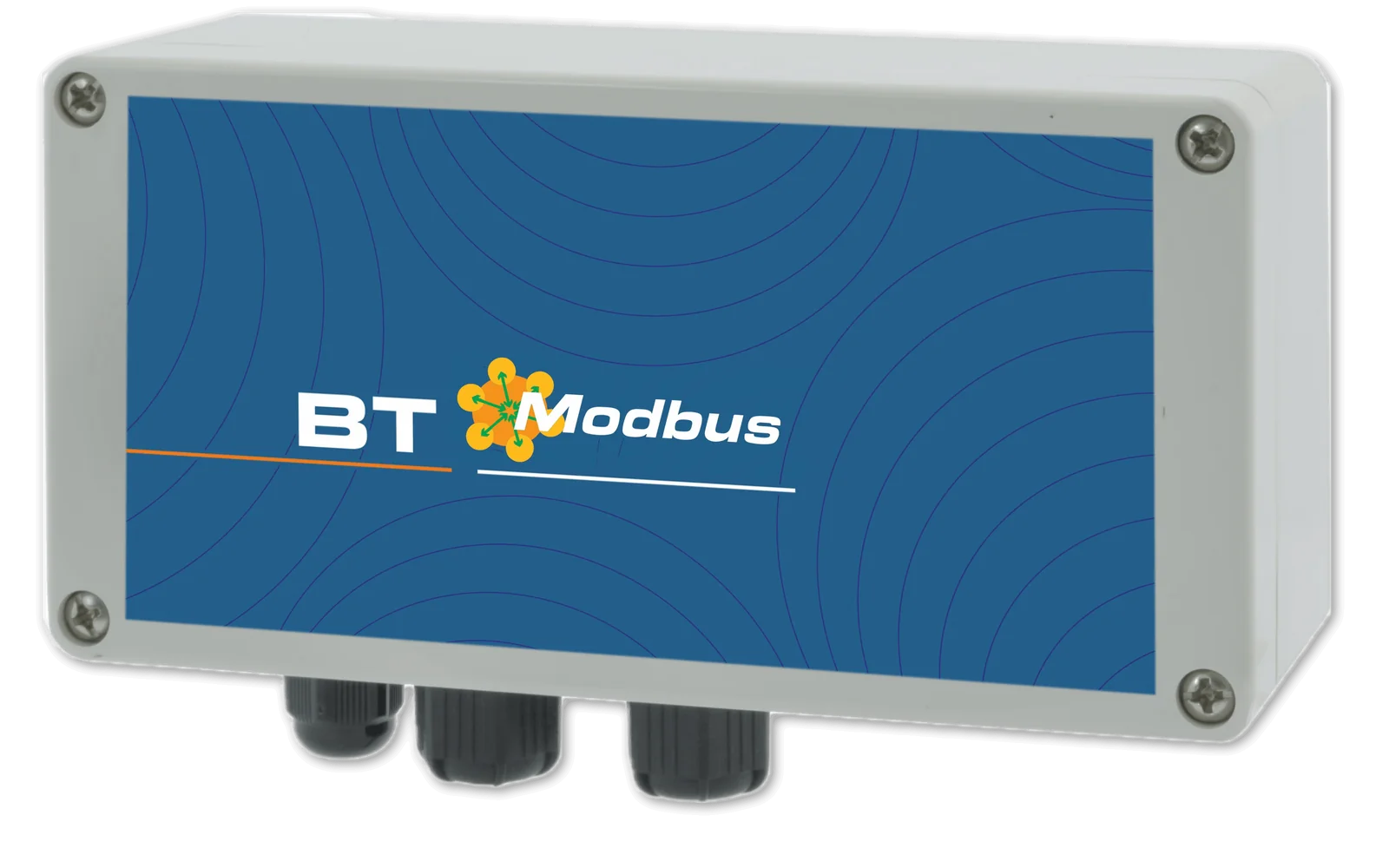
Integration into your PLC: all pump parameters can be managed from your control interface.
A single account brings together all registered installations, each with its own devices: the web portal, free of charge and with no subscription, can be accessed from PC, Mac, tablet and smartphone and allows every parameter to be both viewed and changed, with an encrypted connection and protected access.
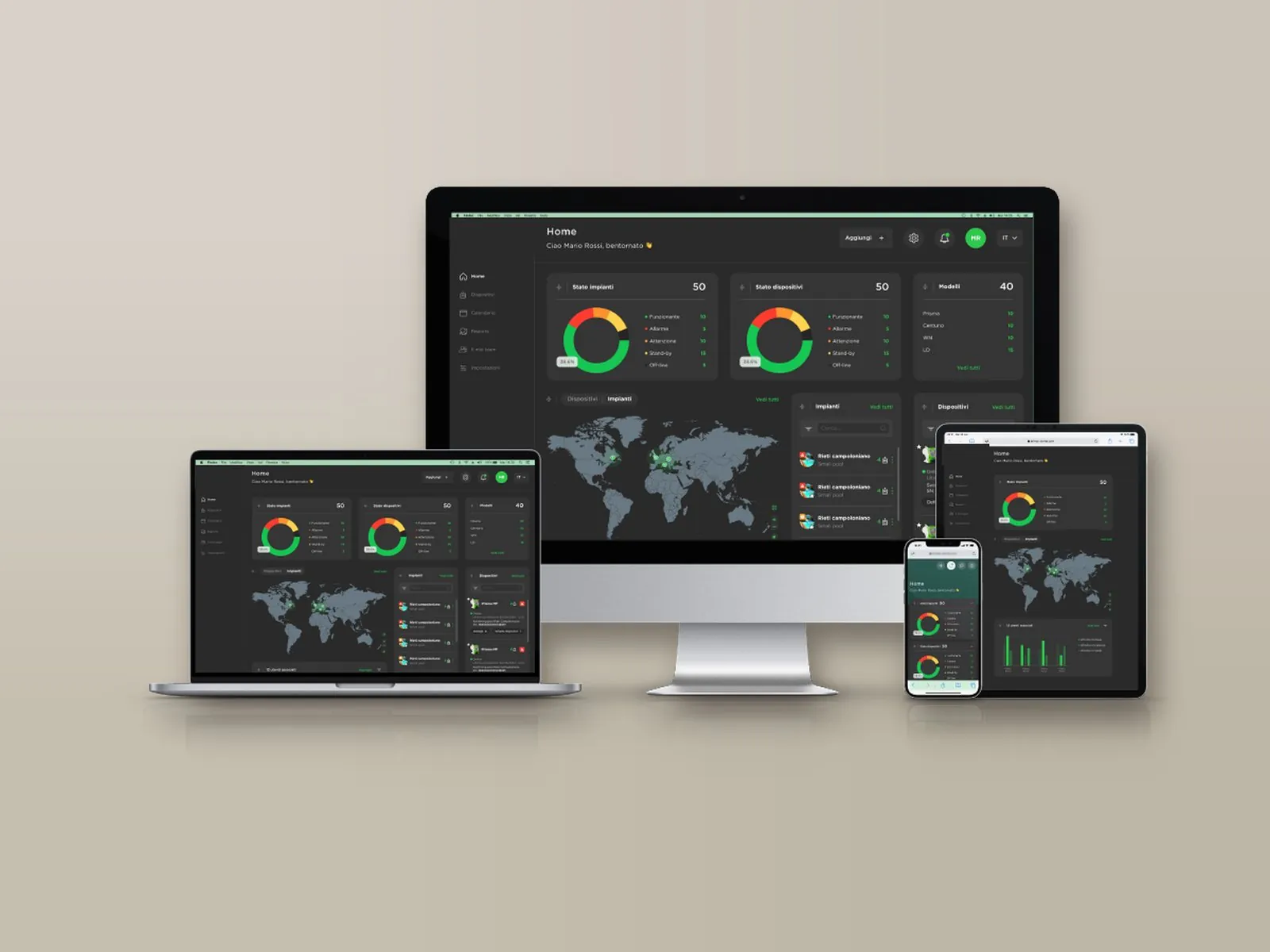
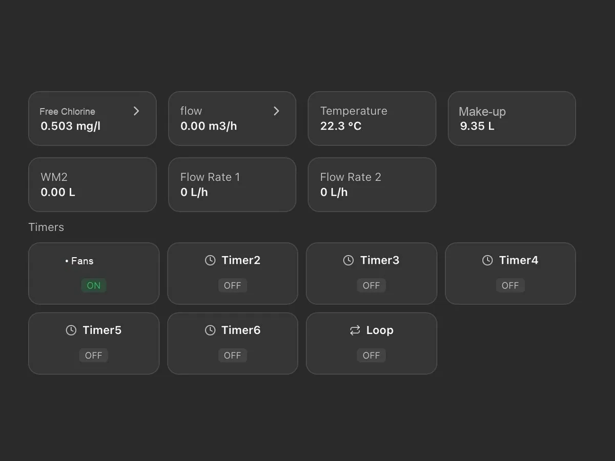
On a single screen: probe readings, chemical levels, pump activation thresholds and active alarms, with the status of installations and devices (normal, warning, alarm, standby, not connected).
Installations appear on an interactive map with their status and open with a click; for each one, the local weather conditions and temperature are also shown.
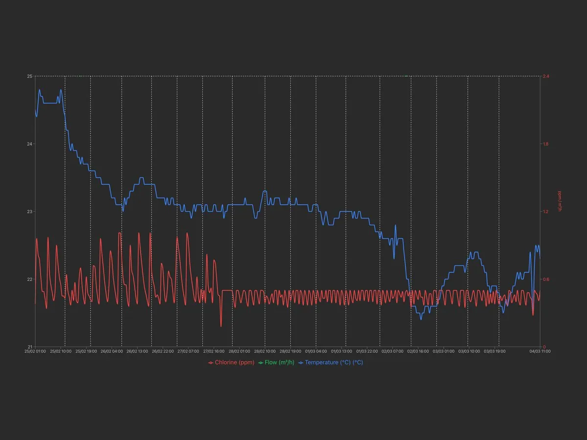
Archive of measurements and alarms, available for consultation at any time with charts and numerical reports exportable in Excel format.
Alarm thresholds for readings, dosing, faulty probe and out-of-range readings, with notification by e-mail or SMS depending on the communication system; a warning is also issued when an installation remains disconnected beyond the set time.
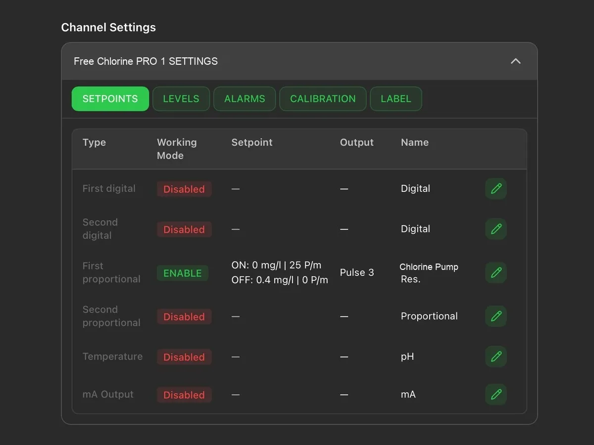
Remote modification of the set points, of the dosing pump activation thresholds and of the corresponding hourly flow rate.
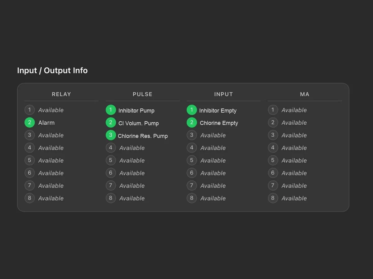
Status of relays, pulse outputs, digital inputs and current outputs, with the name assigned to each connection.
Tasks are scheduled by installation or by device and assigned to technicians; a reminder is sent by e-mail two days before the due date. Each task is shown as scheduled, due, overdue or completed.
The main account has full access and creates the technicians’ accounts, each enabled only for the assigned installations and devices; the last login and activity of each technician are visible.
Reports on devices, tasks and technicians, downloadable in PDF or CSV with the customer’s logo; the log keeps the history of operations and disconnections.
Logo, main colour and light or dark theme; the tiles on the main screen can be rearranged by dragging them. Two installations can be displayed side by side for comparison.
Each device is added through a guided procedure: the model is recognised automatically and associated with the installation, together with the technician to be contacted.
As an alternative to the portal, the Modbus RTU or TCP/IP port allows integration into the plant supervision system.
Performance varies with the diameter of the peristaltic tube.
Suitable for dosing most chemicals.
| Tube (mm) | Max pressure (bar) | Flow rate (l/h) | ml/rev | RPM |
|---|---|---|---|---|
| 1.6 × 1.6 | 2 | 0.018 – 1.8 | 0.3 | 1 – 100 |
| 4.8 × 1.6 | 2 | 0.12 – 12 | 2 | 1 – 100 |
In addition to dosing, the WN pumps also control the water: the messages mainly concern the process; in peristaltic pumps the condition of the tubes is also decisive.
Insight: the pump does not prime and does not dose →| Message | Meaning | Action |
|---|---|---|
| LOW TANK | Chemical tank close to running out. | Check and restore the chemical level in the tank. |
| NO FLOW | The flow contact has stopped the pumps. | Check that there is water flow in the probe holder. |
| FEED LIMIT | Maximum dosing time exceeded without reaching the set point. | Check the pump flow rate and the actual supply of chemical. |
| PROBE FAIL | Probe reading unchanged for too long: the probe is probably damaged. | Check the probe, clean or recalibrate it; if the problem persists, replace it. |
| WAIT pH | pH has priority: the second dosing waits until the pH returns to the correct values. | Normal operating condition; to disable it, change the priority option. |
| DELAY | Dosing suspended: the restart delay countdown is in progress. | Normal operating condition; if not required, reduce the delay in the parameters. |
| POWER SUPPLY OUT OF RANGE | Supply voltage outside the permitted limits. | Check the mains voltage. |
| FEED ON · FEED OFF · OK | Normal operating status: pump dosing, pump stopped, or value at set point. | No action required. |
| WARNING under a channel | The tube of that pump has reached its wear limit (yellow display). | Replace the tube and reset the counter. |
| Calibration reminder | 90 days have passed since the last probe calibration (yellow display, the pump continues to operate). | Recalibrate the probe. |
Green display: normal operation; yellow: warning; red: alarm; white: stand-by. In the event of an alarm or warning, the details can be viewed by turning the knob to STATUS.
The MAINTENANCE menu records the revolutions and operating hours of motors and tubes: when a tube reaches its wear limit, a warning appears below the channel and the display turns yellow. The limits refer to 1 bar of back pressure, 23 °C and chemicals that are not particularly aggressive.
Switch off and disconnect the pump, close the valves and drain the liquid. Open the cover, remove the rotor cover disc and take out the slide with the worn tube; insert the new slide and bring the tube into position by turning the roller holder. Check by hand that it rotates freely, reassemble and carry out a dry test. If the roller holder is removed, the letter “A” must face the operator.
If a motor stops, the status screen shows the corresponding error code (from 1 to 13): by passing it on to our technical support service it is possible to identify immediately whether the problem concerns the power supply, wiring, temperature or communication.
Always enable the maximum dosing time alarm (0 – 100 minutes) and the blocked probe alarm (100 – 254 minutes), and set dosing to stop in the absence of flow: without these protections there is a risk of dangerous overdosing.
If the problem persists, contact us. Before sending the pump for servicing, empty the pump head of chemical and dry it.
The flow rate can be adjusted independently for each pump (or between the pump and the salt chlorinator), so that the correct quantities of pH corrector and disinfectant are dosed according to the probe measurements.
One SET POINT dedicated to pH and one dedicated to the disinfectant (free chlorine, bromine, hydrogen peroxide or Redox).
Priority can be given to pH control, with disinfectant control starting only afterwards, to the benefit of its effectiveness.
The pump is supplied with low-level probes for the tanks: when a chemical runs out, it shows the alarm on the display and activates the corresponding output.
Tell us about your application: our technical staff will recommend the most suitable model, configuration and accessories.
Call or write to us: a technician will reply with a tailored proposal of controllers, pumps, probes and accessories.