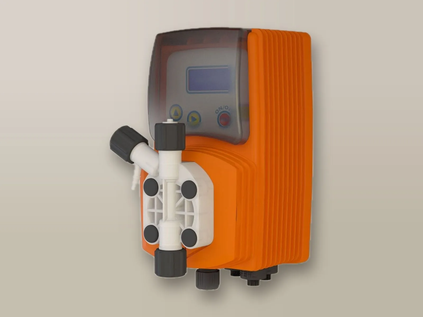
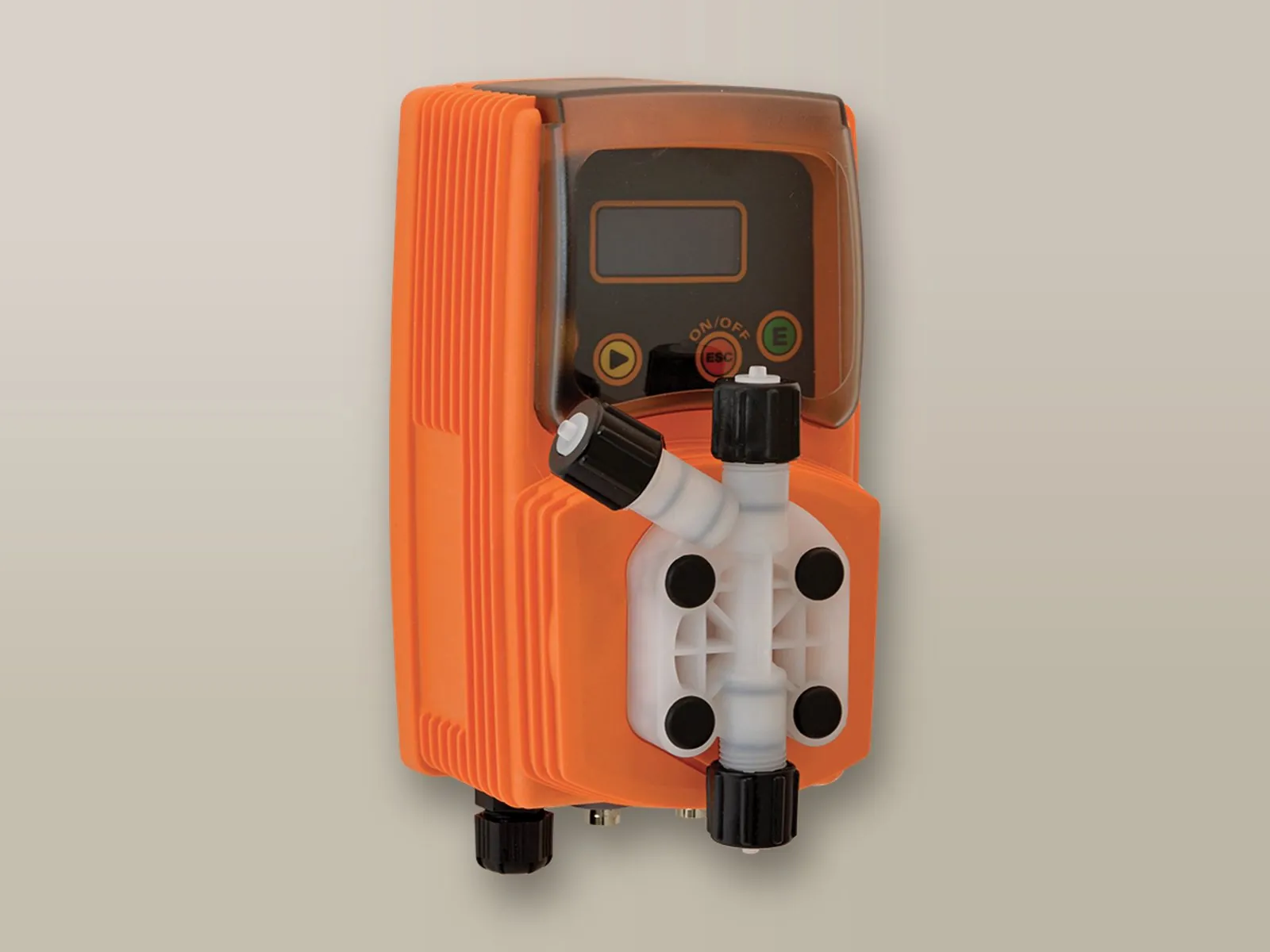
VMS MF
Constant dosing or dosing proportional to 4/20 mA or 0-10 V signals or to a pulse-output water meter.
- Digital constant
- Multiply
- Divide
- PPM
- Millilitres per quintal
- Percentage
- Batch
- mA
- Volt
- Timer
Diaphragm dosing pumps for swimming pools and for civil, sanitary and industrial applications. Electronic adjustment of the injection frequency.
Constant dosing or dosing proportional to 4/20 mA or 0-10 V signals or to a pulse-output water meter.
Pump head: PVDF or PP
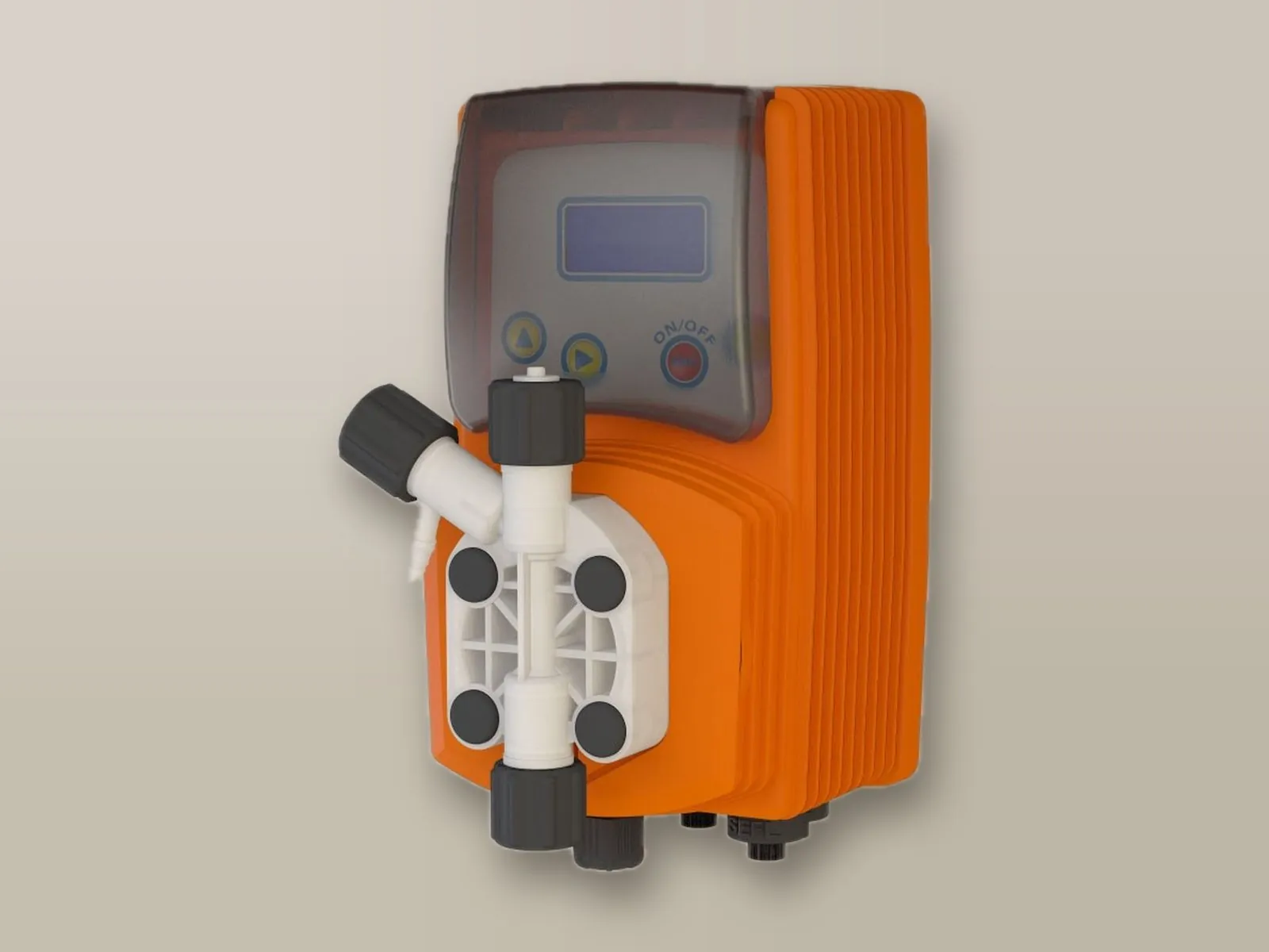
With integrated controller for automatic control of pH or Redox (ORP).
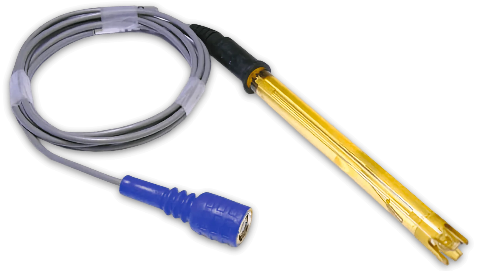 EpHSpH electrode
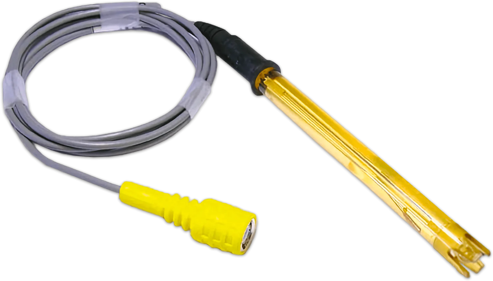 ERhSRedox (ORP) electrode
Pump head: PVDF or PP
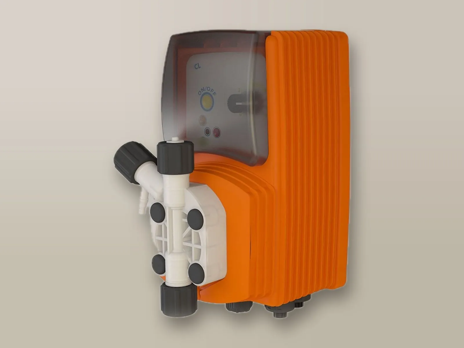
For constant dosing, with input for tank level control.
Pump head: PVDF or PP
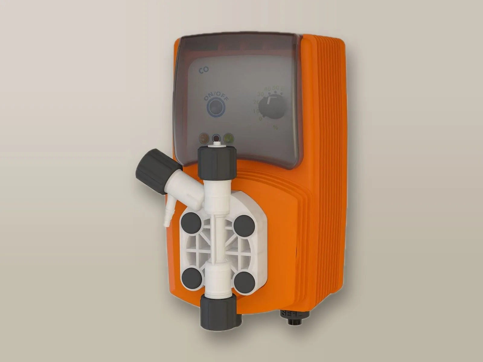
Basic model for constant dosing without external controls.
Pump head: PVDF or PP
State how the pump must dose, the product, the flow rate and the back pressure: the guide proposes the most suitable model and configuration of the series, among those listed in the technical data.
Answer the questions and enter flow rate and back pressure: the recommended model appears below.
| Function | MF | PO | VCL | VCO |
|---|---|---|---|---|
| Dosing modes | ||||
| Constant | – | – | ● | ● |
| Constant with divider | – | – | ● | ● |
| Digital constant | ● | – | – | – |
| Multiply | ● | – | – | – |
| Divide | ● | – | – | – |
| PPM | ● | – | – | – |
| Millilitres per quintal | ● | – | – | – |
| Percentage | ● | – | – | – |
| Batch | ● | – | – | – |
| mA | ● | – | – | – |
| Volt | ● | – | – | – |
| Proportional to pH | – | ● | – | – |
| Proportional to Redox | – | ● | – | – |
| Timer | ● | – | – | – |
| Functions | ||||
| Electronic flow rate adjustment | ● | ● | ● | ● |
| Digital display | ● | ● | – | – |
| Level control | ● | ● | ● | – |
| Stand-by | – | ● | – | – |
| Alarm output | – | ● | – | – |
The pump doses at a constant injection frequency, proportional to the flow rate percentage set with the analogue selector (0 – 100%).
Models: VCL, VCO
Operation similar to constant dosing, with the selector adjustable between 0 and 10%: the maximum flow rate is reduced to as little as 1/10 of the rated value.
Models: VCL, VCO
The pump doses at a constant frequency, determined by the SPH (strokes/hour), SPM (strokes/minute) or LPH (litres/hour) values set during programming.
Models: VMS MF
The pulses from the pulse-output water meter are multiplied by the set factor.
Models: VMS MF
The pulses from the pulse-output water meter are divided by the set factor.
Models: VMS MF
Dosing is calculated from the pulses of the pulse-output water meter and the set PPM value; the concentration of the chemical and the volume per stroke can be programmed.
Models: VMS MF
Dosing is calculated from the pulses of the pulse-output water meter and the set MLQ value (millilitres per quintal).
Models: VMS MF
Dosing is calculated from the pulses of the pulse-output water meter and the set percentage (%).
Models: VMS MF
A pulse from an external contact starts the dosing of the set quantity; pause and work cycles can be programmed.
Models: VMS MF
The 0-4/20 mA current signal controls dosing proportionally, between the set minimum and maximum values.
Models: VMS MF
The 0-10 V voltage signal controls dosing proportionally, between the set minimum and maximum values.
Models: VMS MF
The required pH value (SET POINT) is set: the pump measures the pH by means of a pH electrode and progressively reduces the injection frequency as the set value approaches, stopping when the SET POINT is reached.
Models: VMS PO
The required Redox potential (ORP) (SET POINT) is set: the pump measures it by means of a Redox electrode and progressively reduces the injection frequency as the set value approaches, stopping when the SET POINT is reached.
Models: VMS PO
Up to 16 weekly on/off timers can be programmed, during which the pump doses the set quantity of chemical.
Models: VMS MF
Performance varies with the working back-pressure (head) and with the characteristics of the chemical: for this reason the V and VMS pumps are available in specific configurations.
Suitable for most chemicals: the standard configuration for the most common applications.
| Code | Max pressure (bar) | Max flow rate (l/h) |
|---|---|---|
| VMS 2001 | 20 | 1 |
| VMS 1802 | 18 | 2 |
| VMS 1804 | 18 | 4 |
| VMS 1502 | 15 | 2 |
| VMS 1504 | 15 | 4 |
| VMS 1505 | 15 | 5 |
| VMS 1004 | 10 | 4 |
| VMS 1005 | 10 | 5 |
| VMS 1010 | 10 | 10 |
| VMS 0706 | 7 | 6 |
| VMS 0501 | 5 | 1 |
| VMS 0510 | 5 | 10 |
| VMS 0512 | 5 | 12 |
| VMS 0408 | 4 | 8 |
| VMS 0310 | 3 | 10 |
| VMS 0215 | 2 | 15 |
| VMS 0116 | 1 | 16 |
Required with chemicals that release gas (e.g. peroxides), to prevent the pump from becoming air-locked.
| Code | Max pressure (bar) | Max flow rate (l/h) |
|---|---|---|
| VMSA 1802 | 18 | 2 |
| VMSA 1501 | 15 | 1 |
| VMSA 1503 | 15 | 3 |
| VMSA 1000,5 | 10 | 0.5 |
| VMSA 1003,4 | 10 | 3.4 |
| VMSA 0704 | 7 | 4 |
| VMSA 0507,5 | 5 | 7.5 |
| VMSA 0509 | 5 | 9 |
| VMSA 0405,5 | 4 | 5.5 |
| VMSA 0307 | 3 | 7 |
| VMSA 0212 | 2 | 12 |
| VMSA 0113 | 1 | 13 |
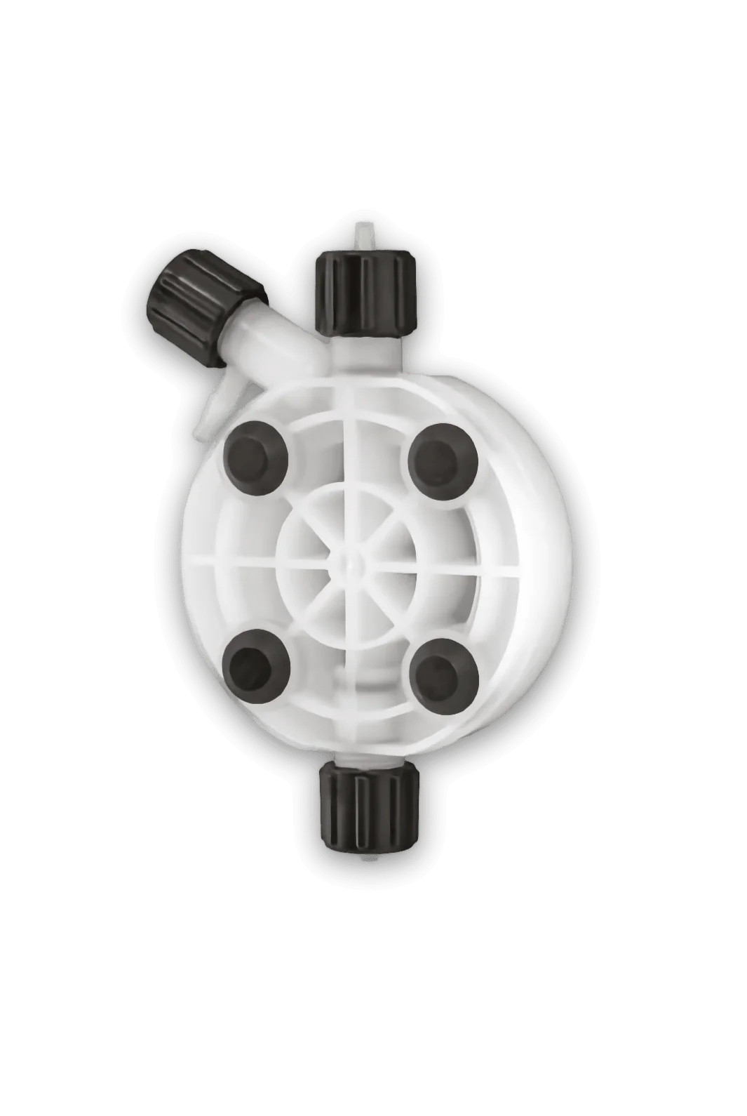
Suitable for most acids, for peroxides and for sodium hypochlorite (chlorine).
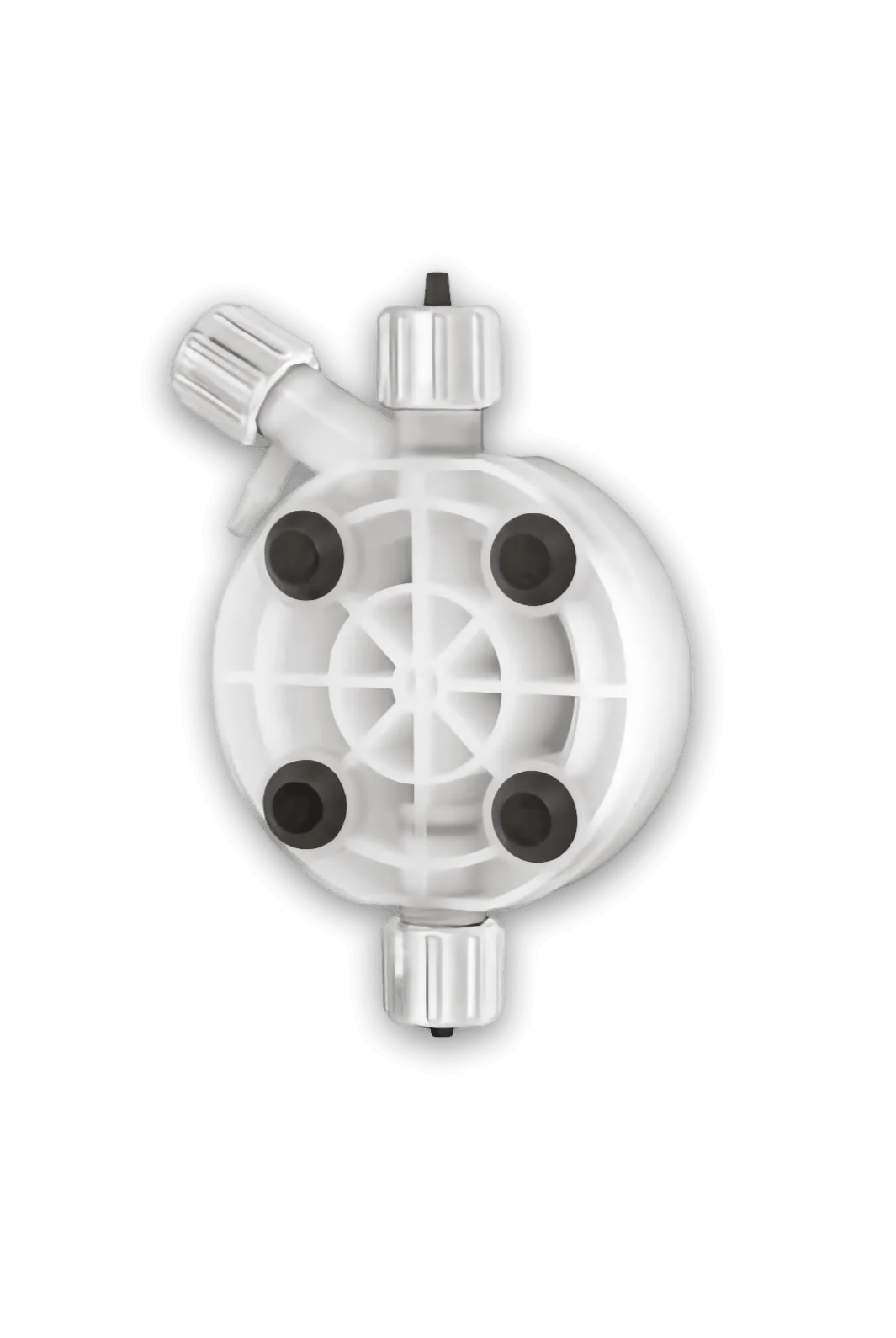
Suitable for sodium hydroxide (caustic soda).
In addition to the standard configuration, versions dedicated to particular applications are available; the performance of each is given in the technical data. The pages by application compare the suitable pumps of all the series.
Self-venting pump head, required with chemicals that release gas (e.g. sodium hypochlorite and peroxides): it vents the gas and prevents the pump from locking.
The most frequent causes of malfunction and the corrective actions to check before contacting technical support.
Insight: the pump does not prime and does not dose →| Message | Meaning | Action |
|---|---|---|
| ALARM LEVEL | Product exhausted in the tank. | Refill the tank. |
| OVER FLOW | The required working frequency exceeds the rated frequency. | Check the data set and the pump flow rate, then switch the pump off and on again. |
| ALARM STROKE | The set flow rate exceeds the rated flow rate. | Check the data set and the flow rate, then switch the pump off and on again. |
| ALARM POWER | The power supply is outside the permitted values. | Check that the voltage matches the rating plate data, then switch the pump off and on again. |
| ALARM BATCH | Batch dosing was interrupted because the external contact changed state. | Check that the connected contact matches the pump setting, then switch the pump off and on again. |
| INPUT OPEN | In mA or Volt mode the input signal is missing. | Check the external signal and its connection. |
| ERROR DATA | The values entered are not consistent. | Check the values; if they are correct and the error persists, the pump is undersized for the required dosing. |
| ERROR MEM | Error in the settings memory. | Restore the factory values with the reset procedure. |
| WRONG ENTRY | Invalid setting, for example the same value for the minimum and the maximum of the signal. | Set distinct, correct values. |
| Incorrect password | The password entered does not match the stored one. | Contact us to unlock it. |
The # symbol on the display indicates one or more active alarms, which can be viewed on the ALARM QTY screen.
| LED | Meaning | Action |
|---|---|---|
| Red, 3 flashes per second | Mains voltage too low. | Check the power supply. |
| Red, 2 flashes per second | Mains voltage too high. | Check the power supply. |
| Steady red | Level alarm: chemical run out (VCL). | Restore the chemical level in the tank. |
| Green, goes off at each stroke | Pump running, normal frequency. | No action required. |
| Orange, goes off at each stroke | Pump running, frequency divided by 10. | No action required. |
| Flashing every 2 seconds | Pump OFF, powered (green; orange in divide mode). | No action required. |
In the 12 – 24 V versions the LED is green only, with the same sequences.
Adjustment is linear between 30 and 100%: below 30% the actual flow rate may differ from the expected one and must therefore be checked.
Connect all the tubing, open the bleed valve and set the adjustment to 100%; start the pump and close the bleed valve as soon as the chemical comes out. With viscous liquids the operation can be assisted with a 20 cc syringe applied to the bleed port.
If the problem persists, contact us. Before sending the pump for servicing, empty the pump head of chemical and dry it.
According to the operating mode and the set parameters, the pump automatically adapts the injection frequency to ensure the required dosing.
The integrated LCD display allows the pump to be programmed and its operating status to be monitored at all times.
Models: VMS MF, VMS PO
The pump is supplied with a low-level probe for the tank: when the chemical runs out, it shows the alarm on the display and activates the corresponding output.
Models: VMS MF, VMS PO, VCL
Pump start and stop can be controlled remotely by means of a run/stop contact from a PLC or another source.
Models: VMS PO
In the event of a fault, a volt-free contact is activated, configurable as normally open (N.O.) or normally closed (N.C.), to drive a visual or audible signalling device, send an SMS or report the event to a PLC.
Models: VMS PO
Tell us about your application: our technical staff will recommend the most suitable model, configuration and accessories.
Call or write to us: a technician will reply with a tailored proposal of controllers, pumps, probes and accessories.