Make-up water and bleed-off
Measurement of the make-up and discharged water with two water meters; bleed-off when the conductivity set point is exceeded, with opening delay, dead band, bleed-off timeout and manual command.
Multi-channel controller with touch screen, designed for the water treatment of cooling towers: it manages up to 10 parameters, bleed-off based on conductivity, antiscalant proportional to the make-up water and two biocides with their activators, with measurement of the make-up and discharged water.
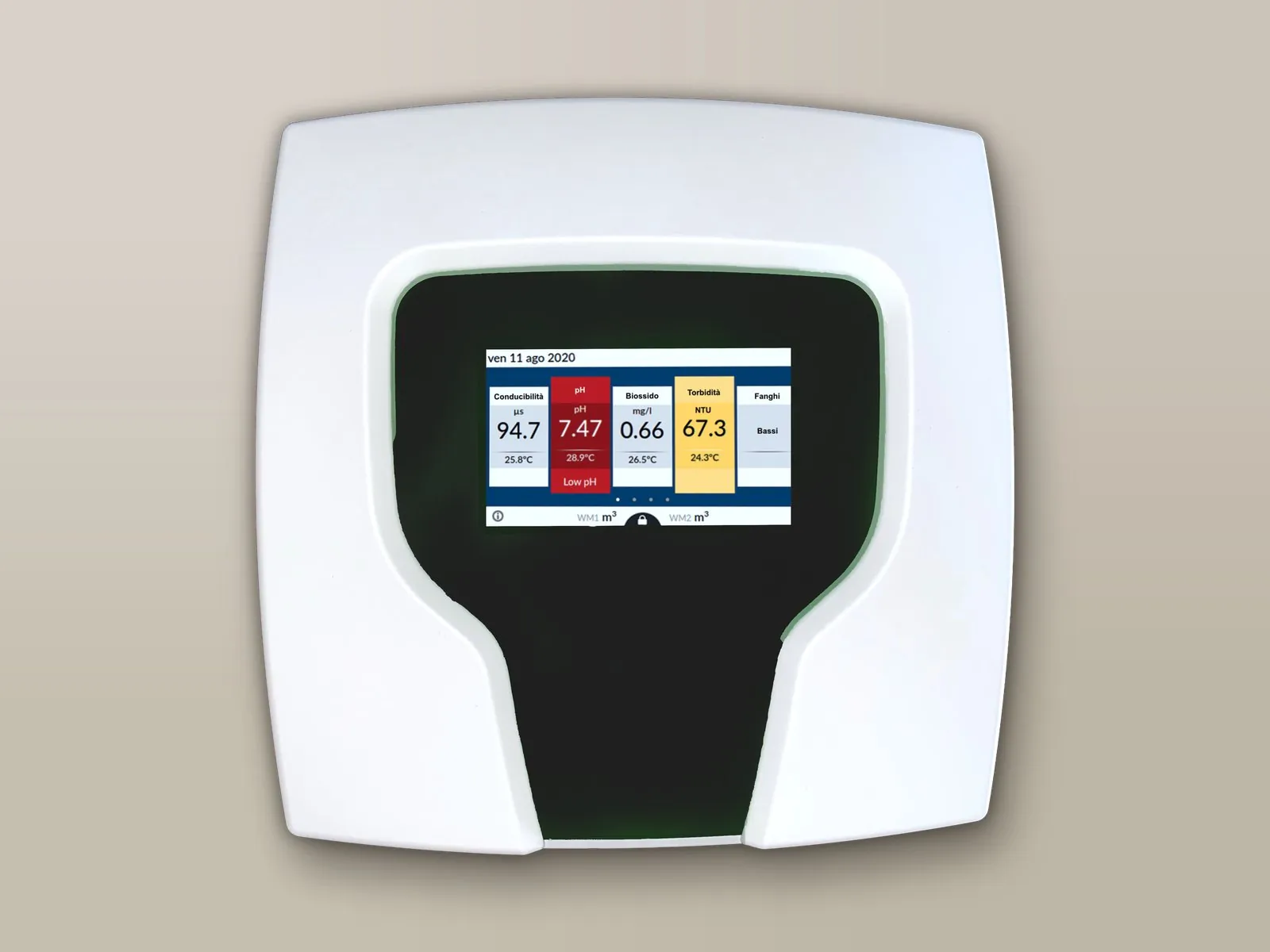
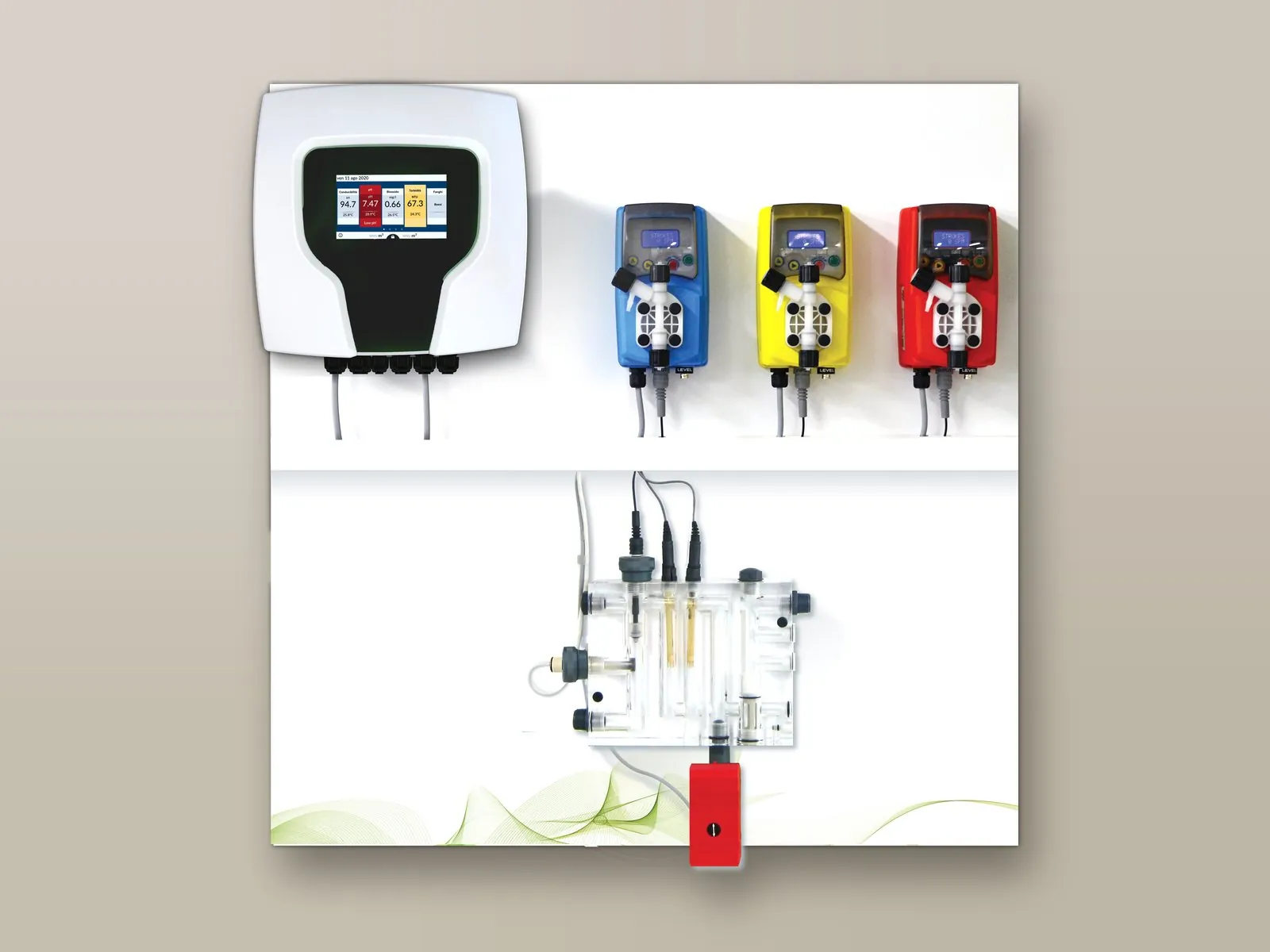
Measurement of the make-up and discharged water with two water meters; bleed-off when the conductivity set point is exceeded, with opening delay, dead band, bleed-off timeout and manual command.
Dosing linked to bleed-off (Feed & Bleed, Feed & % Bleed), to a percentage of time (Feed & % Time) or to the make-up volume, also at constant ppm.
Two biocides and two activators, on a weekly or daily programme, or according to the biocide measurement (residual control).
Discharge of water before the biocide, timed or down to the set conductivity; after dosing, bleed-off remains locked for the set time. On request, start of the circulation pump.
pH control and biocide dosing according to Redox or to the mg/l of chlorine, bromine or chlorine dioxide.
With the corrosion probe and the turbidity meter, the controller continuously verifies the effectiveness of the treatment.
Channel 1 is dedicated to conductivity; channels 2 to 6 are configured with the parameters required by the plant. In addition there are 4 logical channels (turbidity), for a total of 10 parameters.
From the screen the measurements can be read, set points and programmes set and graphs consulted; the recorded data are downloaded to USB.
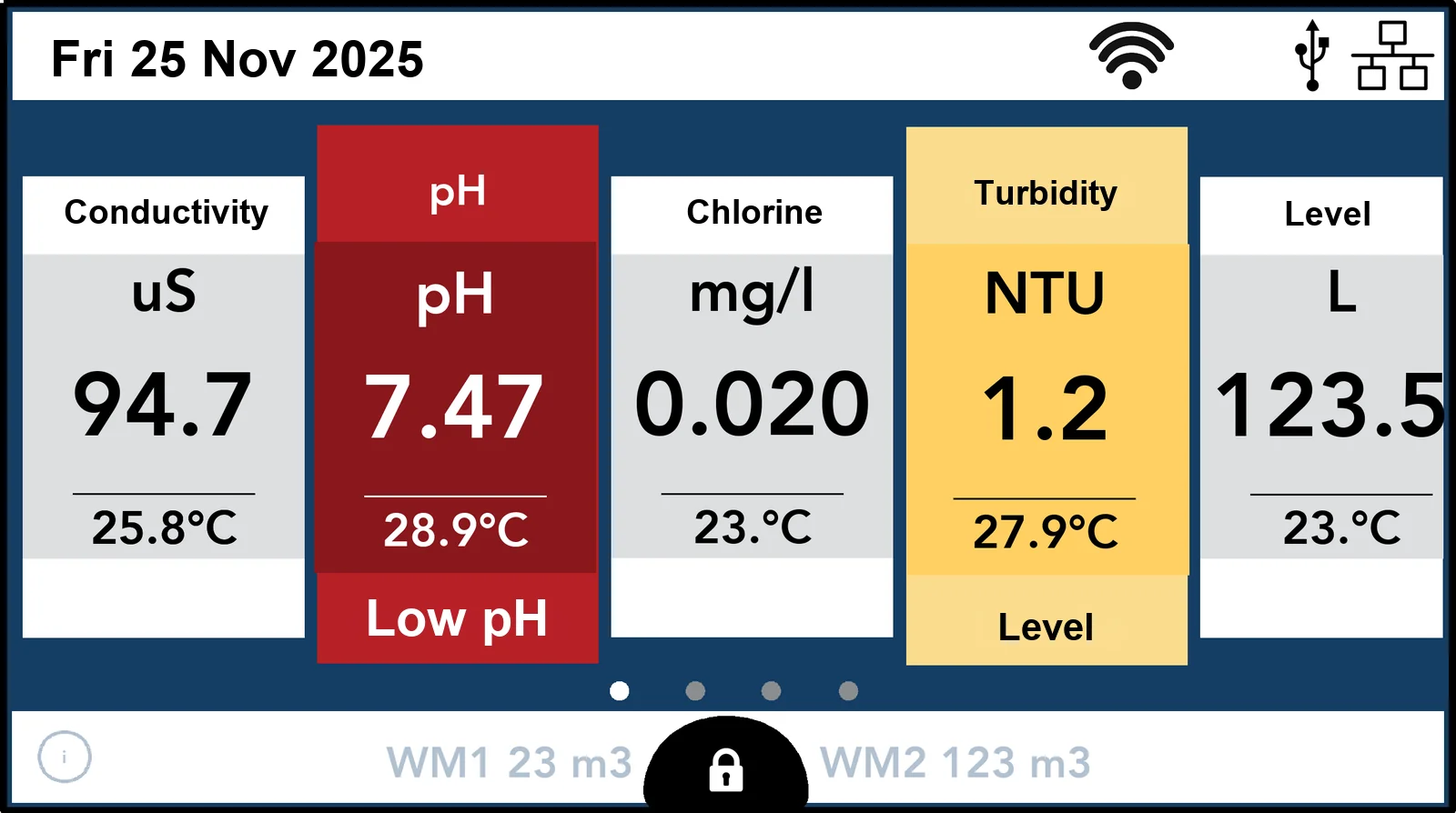
One column for each channel, with unit of measurement, value and temperature; the colour signals alarms, such as low pH.
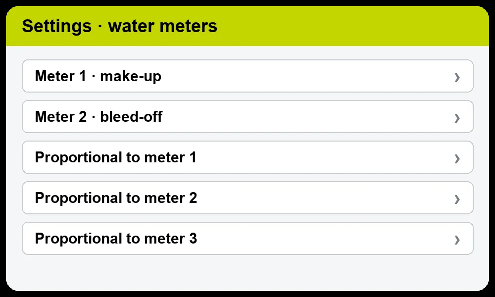
Setting of the two water meters and of the dosing proportional to the volume.
Verification of the actual protection of the plant: continuously by means of a probe, or over the long term by means of coupons.
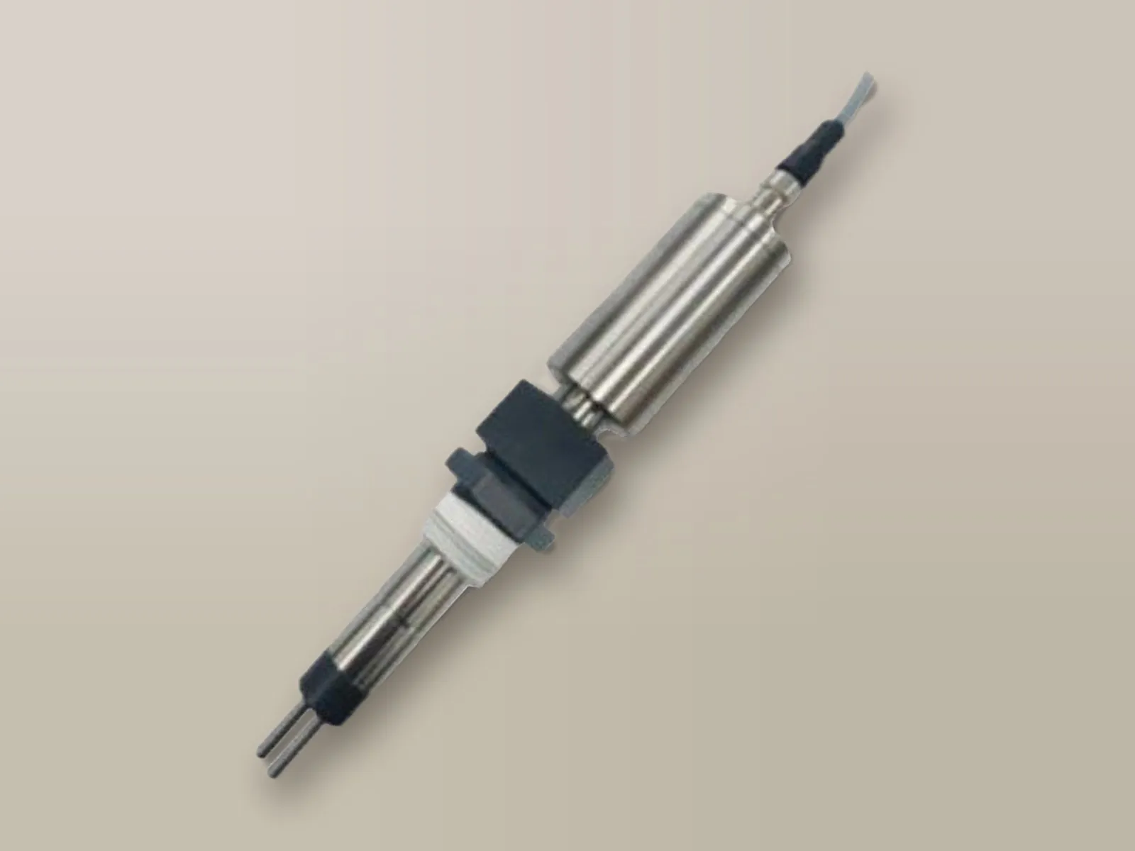
Linear polarisation resistance method, with automatic compensation of conductivity (10 – 10,000 µS/cm) and of electrochemical noise: 0.001 – 10 MPY, general corrosion or specific to steel, copper, 304 stainless steel, brass or aluminium.
Corrosion probe →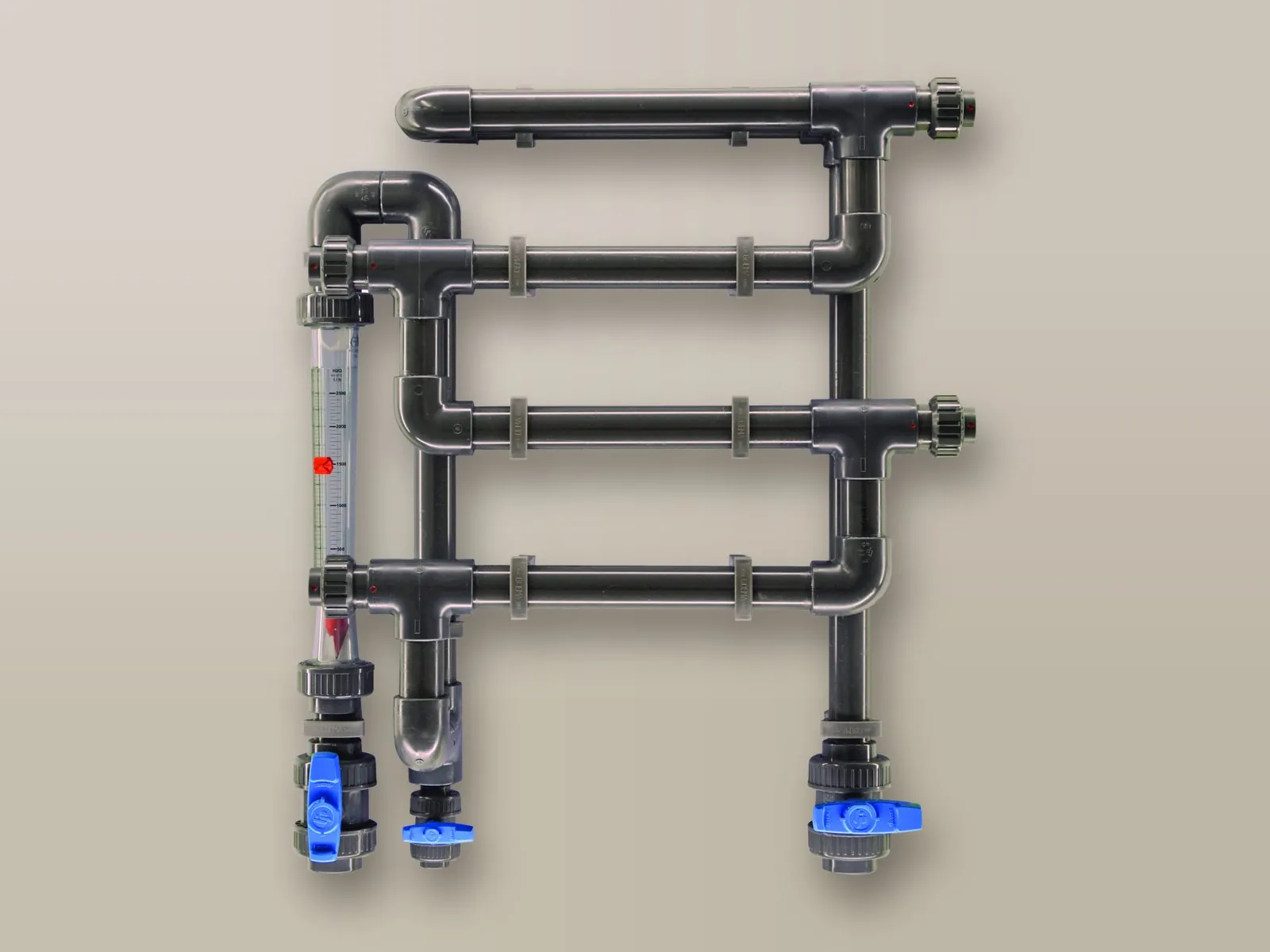
Rack with 4 coupon holders removable without tools, DN40 PN16 pipework, inlet and outlet isolation valves and drain valve; 600 × 900 mm, up to 40 °C.
| Centurio Tower | |
|---|---|
| Parameters | Up to 10, on 6 measuring channels |
| Conductive conductivity | 0.1 µS … 1 S depending on the cell constant |
| Inductive conductivity | 0.1 – 3 … 0.3 – 300 mS |
| pH and Redox | 0 – 14; ±999 mV |
| Chlorine and other biocides | Depending on the cell |
| Tracer | 0 – 300 ppb |
| Corrosion and turbidity | 0.001 – 10 MPY; up to 4,000 NTU |
| Inputs | 8 levels, 2 water meters, flow, RS485 probe, 6 channels |
| Outputs | 8 proportional, 6 ON/OFF, 2 volt-free, 6 current, alarm |
| Communication | Ethernet, Wi-Fi, Modbus RTU and TCP/IP as standard; 4G on request; data on USB |
| Power supply | 230 VAC or 12 – 24 VDC |
The probes are ordered separately, according to the parameters to be measured.
PVDF body, graphite electrodes.
| Model | Mounting | Connection | Range | K factor | Temperature compensation |
|---|---|---|---|---|---|
| ECDC/1 | In-line / by-pass | R3/4" | 0 – 20 mS | 1 | – |
| ECDCC/1 | In-line / by-pass | R3/4" | 0 – 20 mS | 1 | NTC 10K |
| ECDCCPT/1 | In-line / by-pass | R3/4" | 0 – 20 mS | 1 | PT100 |
| ECDC/10 | In-line / by-pass | R3/4" | 0 – 200 mS | 10 | – |
| ECDCC/10 | In-line / by-pass | R3/4" | 0 – 200 mS | 10 | NTC 10K |
| ECDCCPT/10 | In-line / by-pass | R3/4" | 0 – 200 mS | 10 | PT100 |
| ECDCIM/1 | Immersion | G1/2" | 0 – 20 mS | 1 | – |
| ECDCCIM/1 | Immersion | G1/2" | 0 – 20 mS | 1 | NTC 10K |
| ECDCCIMPT/1 | Immersion | G1/2" | 0 – 20 mS | 1 | PT100 |
| ECDCIM/10 | Immersion | G1/2" | 0 – 200 mS | 10 | – |
| ECDCCIM/10 | Immersion | G1/2" | 0 – 200 mS | 10 | NTC 10K |
| ECDCCIMPT/10 | Immersion | G1/2" | 0 – 200 mS | 10 | PT100 |
Operating temperature 1 – 60 °C (100 °C at 2 bar), operating pressure 7 bar (2 bar at 100 °C).
PVDF body, stainless steel electrodes.
| Model | Mounting | Connection | Range | K factor | Temperature compensation |
|---|---|---|---|---|---|
| ECDI/1 | In-line / by-pass | R3/4" | 0 – 5 mS | 1 | – |
| ECDIC/1 | In-line / by-pass | R3/4" | 0 – 5 mS | 1 | NTC 10K |
| ECDICPT/1 | In-line / by-pass | R3/4" | 0 – 5 mS | 1 | PT100 |
| ECDI/01 | In-line / by-pass | R3/4" | 0 – 200 µS | 0.1 | – |
| ECDIC/01 | In-line / by-pass | R3/4" | 0 – 200 µS | 0.1 | NTC 10K |
| ECDICPT/01 | In-line / by-pass | R3/4" | 0 – 200 µS | 0.1 | PT100 |
| ECDIIM/1 | Immersion | G1/2" | 0 – 5 mS | 1 | – |
| ECDICIM/1 | Immersion | G1/2" | 0 – 5 mS | 1 | NTC 10K |
| ECDICPTIM/1 | Immersion | G1/2" | 0 – 5 mS | 1 | PT100 |
| ECDIIM/01 | Immersion | G1/2" | 0 – 200 µS | 0.1 | – |
| ECDIIM/02 | Immersion | G1/2" | 0 – 500 µS | 0.2 | – |
| ECDICIM/01 | Immersion | G1/2" | 0 – 200 µS | 0.1 | NTC 10K |
| ECDICPTIM/01 | Immersion | G1/2" | 0 – 200 µS | 0.1 | PT100 |
Operating temperature 1 – 60 °C (100 °C at 2 bar), operating pressure 7 bar (2 bar at 100 °C).
Epoxy body, platinum electrodes, diameter 12 mm.
| Model | Mounting | Range | K factor | Temperature compensation |
|---|---|---|---|---|
| ECDHL/1 | In-line / by-pass | 0.2 – 20 mS | 1 | – |
| ECDHLC/1 | In-line / by-pass | 0.2 – 20 mS | 1 | NTC 10K |
| ECDHLCPT/1 | In-line / by-pass | 0.2 – 20 mS | 1 | PT100 |
| ECDHL/01 | In-line / by-pass | 0 – 200 µS | 0.1 | – |
| ECDHLC/01 | In-line / by-pass | 0 – 200 µS | 0.1 | NTC 10K |
| ECDHLCPT/01 | In-line / by-pass | 0 – 200 µS | 0.1 | PT100 |
| ECDHL/10 | In-line / by-pass | 20 – 200 mS | 10 | – |
| ECDHLC/10 | In-line / by-pass | 20 – 200 mS | 10 | NTC 10K |
| ECDHLCPT/10 | In-line / by-pass | 20 – 200 mS | 10 | PT100 |
Operating temperature 1 – 70 °C, operating pressure 7 bar.
Stainless steel body and electrodes, R3/4" connection, in-line or by-pass mounting.
| Model | Range | K factor | Temperature compensation | Operating temperature |
|---|---|---|---|---|
| EICDC/1 | 0 – 20 mS | 1 | NTC 10K | 1 – 130 °C |
| EICDCPT/1 | 0 – 20 mS | 1 | PT100 | 1 – 130 °C |
| EICDC/01 | 0 – 200 µS | 0.1 | NTC 10K | 1 – 130 °C |
| EICDCPT/01 | 0 – 200 µS | 0.1 | PT100 | 1 – 130 °C |
| EICDC/001 | 0 – 20 µS | 0.01 | NTC 10K | 1 – 130 °C |
| EICDCPT/001 | 0 – 20 µS | 0.01 | PT100 | 1 – 130 °C |
| EICDCHPT/1 | 0 – 20 mS | 1 | PT100 | 1 – 200 °C |
| EICDCHPT/01 | 0 – 200 µS | 0.1 | PT100 | 1 – 200 °C |
| EICDCHPT/001 | 0 – 20 µS | 0.01 | PT100 | 1 – 200 °C |
Operating pressure 15 bar.
| ECDINDPT | ECDSINDPT | |
|---|---|---|
| Measuring range | 0.3 – 3 mS 0.3 – 30 mS 0.3 – 300 mS | 0.3 – 10 mS |
| Measuring system | Inductive | Inductive |
| Body | PEEK | PEEK |
| Mounting | In-line / by-pass / immersion | In-line / by-pass / immersion |
| Temperature compensation | PT100 | PT100 |
| Operating temperature | 1 – 85 °C (100 °C for temporary measurement) | 1 – 85 °C (100 °C for temporary measurement) |
| Operating pressure | 8 bar | 8 bar |
| Electrode | Pressure | Connection | Body | Minimum conductivity | Junction | Temperature | Cable | Diameter | Notes |
|---|---|---|---|---|---|---|---|---|---|
| EPHS | 7 bar (3.5 bar) | BNC | Epoxy | 100 µS | – | 70 °C (80 °C) | 0.8 m | 12 mm | – |
| EPHM | 7 bar (3.5 bar) | BNC | Epoxy | 100 µS | – | 70 °C (80 °C) | 4.5 m | 12 mm | – |
| EPHL | 7 bar (3.5 bar) | BNC | Epoxy | 100 µS | – | 70 °C (80 °C) | 15 m | 12 mm | – |
| EPHSN6 | 7 bar (3.5 bar) | SN6 with PG13.5 thread | Epoxy | 100 µS | – | 70 °C (80 °C) | 1 – 100 m | 12 mm | – |
| EPHMD/100 | 7 bar | BNC | Epoxy | 100 µS | Double | 100 °C | 4.5 m | 12 mm | – |
| EPHM/D | 7 bar (3.5 bar) | BNC | Epoxy | 100 µS | Double | 70 °C (80 °C) | 4.5 m | 12 mm | – |
| EPHM/D/SN6 | 7 bar (3.5 bar) | SN6 with PG13.5 thread | Epoxy | 100 µS | Double | 70 °C (80 °C) | 1 – 100 m | 12 mm | – |
| EPHMD/LI | 7 bar (3.5 bar) | SN6 with PG13.5 thread | Epoxy | 3 µS | Double | 70 °C (80 °C) | 1 – 100 m | 12 mm | For low-conductivity water |
| EPHSC | 7 bar (3.5 bar) | BNC | Epoxy | 100 µS | Double | 70 °C (80 °C) | 4.5 m | 12 mm | Self-cleaning |
| EPHSC/SN6 | 7 bar (3.5 bar) | SN6 with PG13.5 thread | Epoxy | 100 µS | Double | 70 °C (80 °C) | 1 – 100 m | 12 mm | Self-cleaning |
| EPHM/HF | 7 bar (3.5 bar) | BNC | Epoxy | 100 µS | Double | 70 °C (80 °C) | 4.5 m | 12 mm | Resistant to 1% hydrofluoric acid |
| EPHSN6 GK | 10 bar | SN6 | Glass | 150 µS | – | −5 / 135 °C | 1 – 100 m | 12 mm | High temperature |
All models: combination electrode, range 0 – 14 pH, resolution 0.01.
| Electrode | Range | Pressure | Connection | Body | Minimum conductivity | Junction | Temperature | Cable | Diameter | Notes |
|---|---|---|---|---|---|---|---|---|---|---|
| ERhS | ± 1,000 mV | 7 bar (3.5 bar) | BNC | Epoxy | 100 µS | – | 70 °C (80 °C) | 0.8 m | 12 mm | – |
| ERhM | ± 1,000 mV | 7 bar (3.5 bar) | BNC | Epoxy | 100 µS | – | 70 °C (80 °C) | 4.5 m | 12 mm | – |
| ERhL | ± 1,000 mV | 7 bar (3.5 bar) | BNC | Epoxy | 100 µS | – | 70 °C (80 °C) | 15 m | 12 mm | – |
| ERhHLB SN6 | ± 1,500 mV | 6 bar | SN6 with PG13.5 thread | Glass | 100 µS | – | 80 °C | 10 m | 12 mm | High linearity and sensitivity, for low chlorine concentrations |
| ERhSN6 | ± 1,000 mV | 7 bar | SN6 with PG13.5 thread | Epoxy | 100 µS | – | 100 °C | 1 – 100 m | 12 mm | – |
| ERhMD/100 | ± 1,000 mV | 7 bar | BNC | Epoxy | 100 µS | Double | 100 °C | 4.5 m | 12 mm | – |
| ERhM/D | ± 1,000 mV | 7 bar (3.5 bar) | BNC | Epoxy | 100 µS | Double | 70 °C (80 °C) | 4.5 m | 12 mm | – |
| ERhSC | ± 1,000 mV | 7 bar (3.5 bar) | BNC | Epoxy | 100 µS | Double | 70 °C (80 °C) | 4.5 m | 12 mm | Self-cleaning |
| ERhSC/SN6 | ± 1,000 mV | 7 bar (3.5 bar) | SN6 with PG13.5 thread | Epoxy | 100 µS | Double | 70 °C (80 °C) | 1 – 100 m | 12 mm | Self-cleaning |
All models: combination electrode, resolution 1 mV.
| SCL3N/0.5 | SCL3N/2 | SCL3N/20 | SCL18/0.5 | SCL18/2 | SCL18/20 | SCL3S/20 | |
|---|---|---|---|---|---|---|---|
| Measuring range | 0 – 0.5 mg/l | 0 – 2 mg/l | 0 – 20 mg/l | 0 – 0.5 mg/l | 0 – 2 mg/l | 0 – 20 mg/l | 0 – 20 mg/l |
| Resolution | 0.001 | 0.001 | 0.01 | 0.001 | 0.001 | 0.01 | 0.01 |
| Free chlorine | Inorganic | Inorganic | Inorganic | Inorganic | Inorganic | Inorganic | Organic and inorganic |
| Water | Fresh | Fresh | Fresh | Fresh | Fresh | Fresh | Fresh or salt |
| Electrodes | 2 | 2 | 2 | 3 | 3 | 3 | 2 |
| Selective membrane | Yes | Yes | Yes | No | No | No | Yes |
| Automatic compensation | pH and temperature | pH and temperature | pH and temperature | pH and temperature | pH and temperature | pH and temperature | Temperature |
| Self-cleaning | – | – | – | Yes | Yes | Yes | – |
| Operating pH | 5 – 9.5 | 5 – 9.5 | 5 – 9.5 | 5 – 9 | 5 – 9 | 5 – 9 | 5.5 – 9.5 |
| Operating temperature | 1 – 40 °C | 1 – 40 °C | 1 – 40 °C | 5 – 70 °C | 5 – 70 °C | 5 – 70 °C | 5 – 45 °C |
| Operating pressure | 1 bar | 1 bar | 1 bar | 8 bar | 8 bar | 8 bar | 1 bar |
| Water flow | 30 l/h | 30 l/h | 30 l/h | 40 l/h | 40 l/h | 40 l/h | 30 l/h |
| SCL2/0.5 | SCL2/2 | SCL2/20 | SCL17/0.5 | SCL17/2 | SCL17/20 | |
|---|---|---|---|---|---|---|
| Measuring range | 0 – 0.5 mg/l | 0 – 2 mg/l | 0 – 20 mg/l | 0 – 0.5 mg/l | 0 – 2 mg/l | 0 – 20 mg/l |
| Resolution | 0.001 | 0.001 | 0.01 | 0.001 | 0.001 | 0.01 |
| Electrodes | 2 | 2 | 2 | 3 | 3 | 3 |
| Selective membrane | Yes | Yes | Yes | No | No | No |
| Self-cleaning | – | – | – | Yes | Yes | Yes |
| Operating pH | 1 – 6 | 1 – 6 | 1 – 6 | 5 – 9 | 5 – 9 | 5 – 9 |
| Operating temperature | 1 – 40 °C | 1 – 40 °C | 1 – 40 °C | 5 – 70 °C | 5 – 70 °C | 5 – 70 °C |
| Operating pressure | 1 bar | 1 bar | 1 bar | 8 bar | 8 bar | 8 bar |
| Water flow | 30 l/h | 30 l/h | 30 l/h | 40 l/h | 40 l/h | 40 l/h |
Automatic temperature compensation on all models.
| SCL8/2 | SCL8/20 | SBR/20 | SCL9 | SCL11/200 | SCL11/2000 | SCL10 | SCT | |
|---|---|---|---|---|---|---|---|---|
| Measurement | Total chlorine | Total chlorine | Bromine | Hydrogen peroxide | Peracetic acid | Peracetic acid | Ozone | Chlorites |
| Measuring range | 0 – 2 mg/l | 0 – 20 mg/l | 0 – 20 mg/l | 0 – 200 mg/l | 0 – 200 mg/l | 0 – 2,000 mg/l | 0 – 20 mg/l | 0 – 2 mg/l |
| Resolution | 0.001 | 0.01 | 0.01 | 0.1 | 0.1 | 1 | 0.01 | 0.001 |
| Operating pH | 4 – 12 | 4 – 12 | 6.5 – 9.5 | 1 – 11 | 1 – 6 | 1 – 6 | 2 – 11 | 5.5 – 9.5 |
| Operating pressure | 1 bar | 1 bar | 0.5 bar | 1 bar | 1 bar | 1 bar | 1 bar | 1 bar |
All models: 2 electrodes, selective membrane, automatic temperature compensation, operating temperature 1 – 40 °C, water flow 30 l/h.
| ETRC2 | |
|---|---|
| Measuring range | 0 – 300 ppb of PTSA |
| Error | ± 1 ppb or 5% of reading |
| Sensitivity | 1 ppb |
| Linearity | 0.99 r² |
| Signal source | LED |
| Detection | Photodiode |
| Response time | 5 seconds |
| Sample pressure | 100 psi (approx. 7 bar) |
| Sample temperature | 4 – 40 °C |
| Ambient temperature | 4 – 49 °C |
| Output | 4-20 mA and RS-485 Modbus RTU |
| Power supply | 24 VDC (± 2 V), 65 mA |
| Body | PVC |
| E-CORR COLD | E-CORR HOT | |
|---|---|---|
| General corrosion | 0.001 – 10 MPY | 0.001 – 995 MPY |
| Localised corrosion | index 0 – 100 | index 0 – 100 |
| Resolution | 0.001 MPY | 0.001 MPY or 1% of reading |
| Conductivity compensation | 10 – 10,000 µS/cm | 10 – 50,000 µS/cm |
| Reading interval | 1, 2, 5 or 20 min | 3 – 1,440 min |
| Alloy factor | 0 – 3 | 0 – 3 |
| Operating temperature | −10 / +50 °C | −10 / +240 °C |
| Operating pressure | 7 bar | 34.5 bar |
| Power supply | 24 VDC, 2 W | 24 VDC, 2 W |
| Outputs | 2 × 4/20 mA (general and localised), RS485 | 2 × 4/20 mA (general and localised), RS485 Modbus |
| Installation | In-line, NPT threaded connection | In-line, 3/4" NPT or BSP connection |
| Body | AISI 304 | Titanium and PEEK |
| Dimensions | 281.5 mm, Ø 23 / 43 mm | 280 mm, Ø 52 mm |
| Weight | 687 g | 1,150 g |
| Cable | 1.5 m, extensions available | 1.5 m, extensions available |
| Protection | IP65 | IP68 |
| ETORB2 | |
|---|---|
| Measuring range | 0/40 NTU – 0/400 NTU – 0/4,000 NTU |
| Measurement error | ± 5% of reading |
| Measuring system | NIR scattered light at 90°, nephelometric principle |
| Body | PVC |
| Optical window | Sapphire glass |
| Automatic compensation | Temperature |
| Self-cleaning | Yes (water jet, max 1 bar) |
| Operating temperature | 0 – 40 °C |
| Operating pressure | 2 bar |
The controllers can be remotely controlled bidirectionally (read and write) from the web portal, from PC, tablet and smartphone: viewing of measurements, modification of set points, dosing and alarms, receipt of alarms and download of logs. Alternatively, integration into your PLC via Modbus is possible.

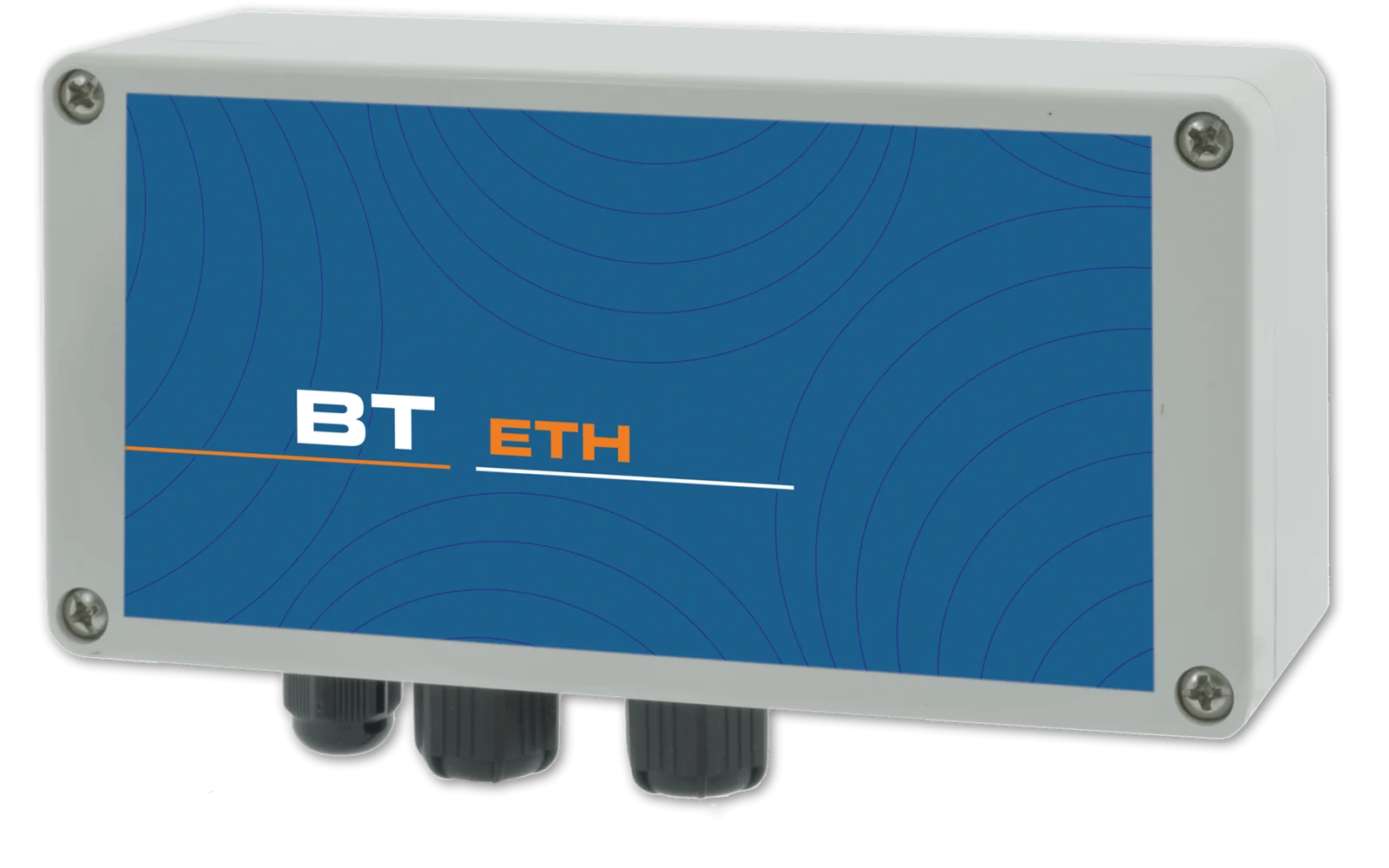
Connection to the web portal via network cable: measurements, set points, dosing and alarms accessible from PC, tablet and smartphone.
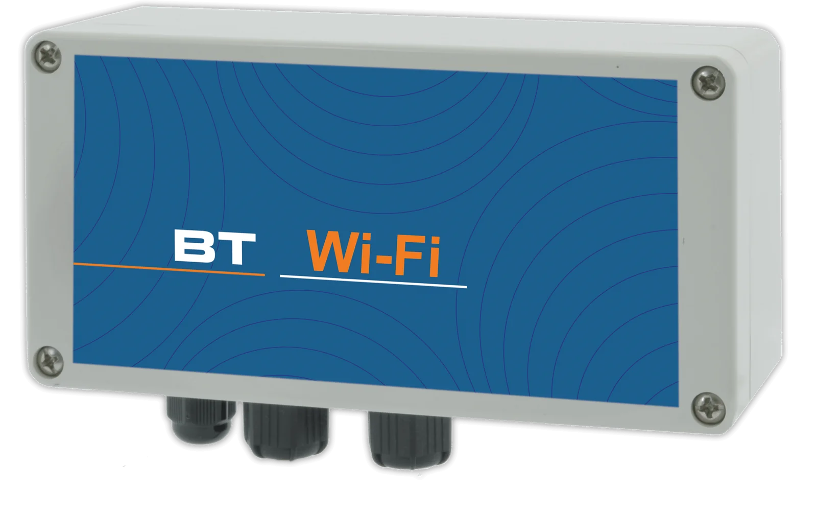
Wireless connection to the web portal, with the same functions as the cable connection.

Download of the logged data to a USB memory stick, for archiving and analysis with a spreadsheet.
Integration into your PLC via serial port.
Integration into your PLC or SCADA via Ethernet network.

Current signal proportional to the measured value, for remote monitoring or for controlling pumps and other instrumentation.
Connection via the cellular network for installations without a local network, with alarm notification by SMS or e-mail.
Ethernet, Wi-Fi, USB, Modbus RTU, Modbus TCP/IP and 4/20 mA outputs as standard; 4G modem optional.
A single account brings together all registered installations, each with its own devices: the web portal, free of charge and with no subscription, can be accessed from PC, Mac, tablet and smartphone and allows every parameter to be both viewed and changed, with an encrypted connection and protected access.
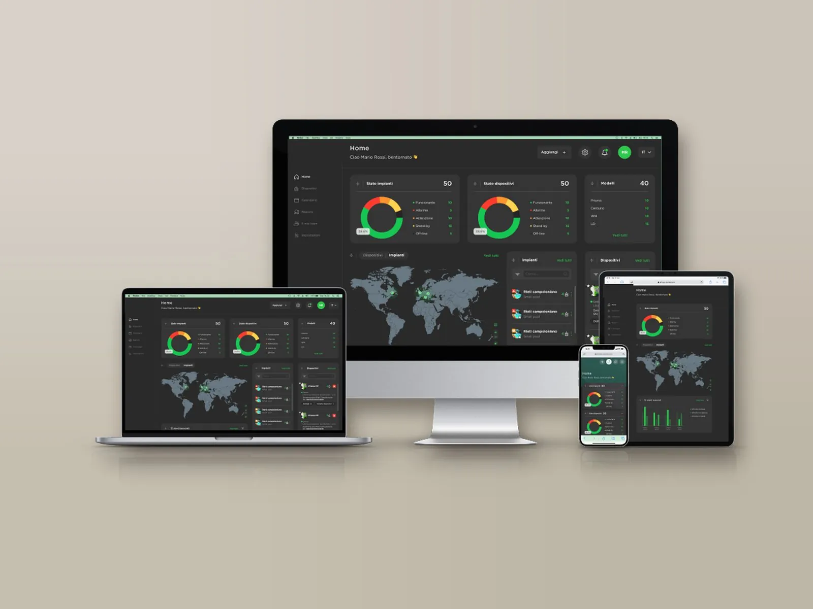
On a single screen: probe readings, chemical levels, pump activation thresholds and active alarms, with the status of installations and devices (normal, warning, alarm, standby, not connected).
Installations appear on an interactive map with their status and open with a click; for each one, the local weather conditions and temperature are also shown.
Archive of measurements and alarms, available for consultation at any time with charts and numerical reports exportable in Excel format.
Alarm thresholds for readings, dosing, faulty probe and out-of-range readings, with notification by e-mail or SMS depending on the communication system; a warning is also issued when an installation remains disconnected beyond the set time.
Remote modification of the set points, of the dosing pump activation thresholds and of the corresponding hourly flow rate.
Status of relays, pulse outputs, digital inputs and current outputs, with the name assigned to each connection.
Tasks are scheduled by installation or by device and assigned to technicians; a reminder is sent by e-mail two days before the due date. Each task is shown as scheduled, due, overdue or completed.
The main account has full access and creates the technicians’ accounts, each enabled only for the assigned installations and devices; the last login and activity of each technician are visible.
Reports on devices, tasks and technicians, downloadable in PDF or CSV with the customer’s logo; the log keeps the history of operations and disconnections.
Logo, main colour and light or dark theme; the tiles on the main screen can be rearranged by dragging them. Two installations can be displayed side by side for comparison.
Each device is added through a guided procedure: the model is recognised automatically and associated with the installation, together with the technician to be contacted.
As an alternative to the portal, the Modbus RTU or TCP/IP port allows integration into the plant supervision system.
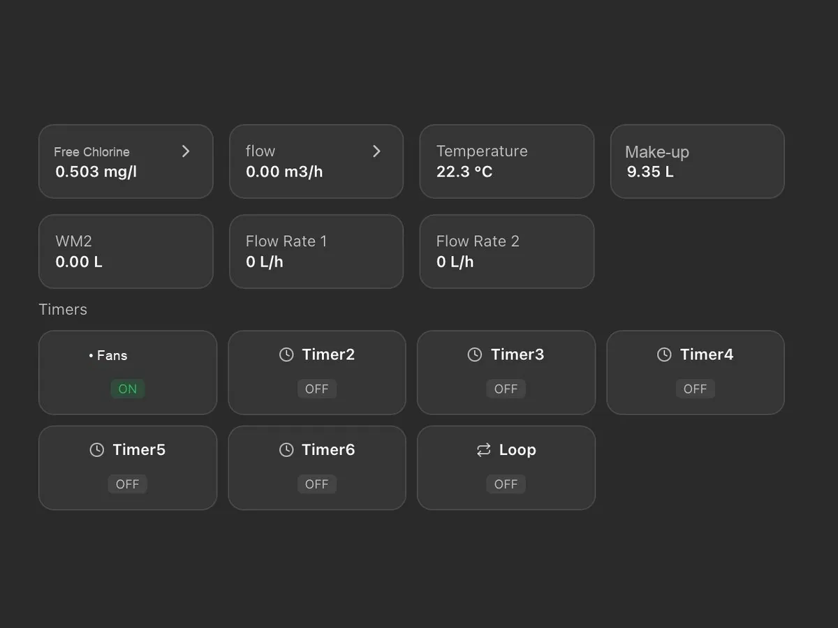
Controller, probe holder, bleed-off valve, water meters and dosing pumps pre-assembled.
Panels for cooling towers →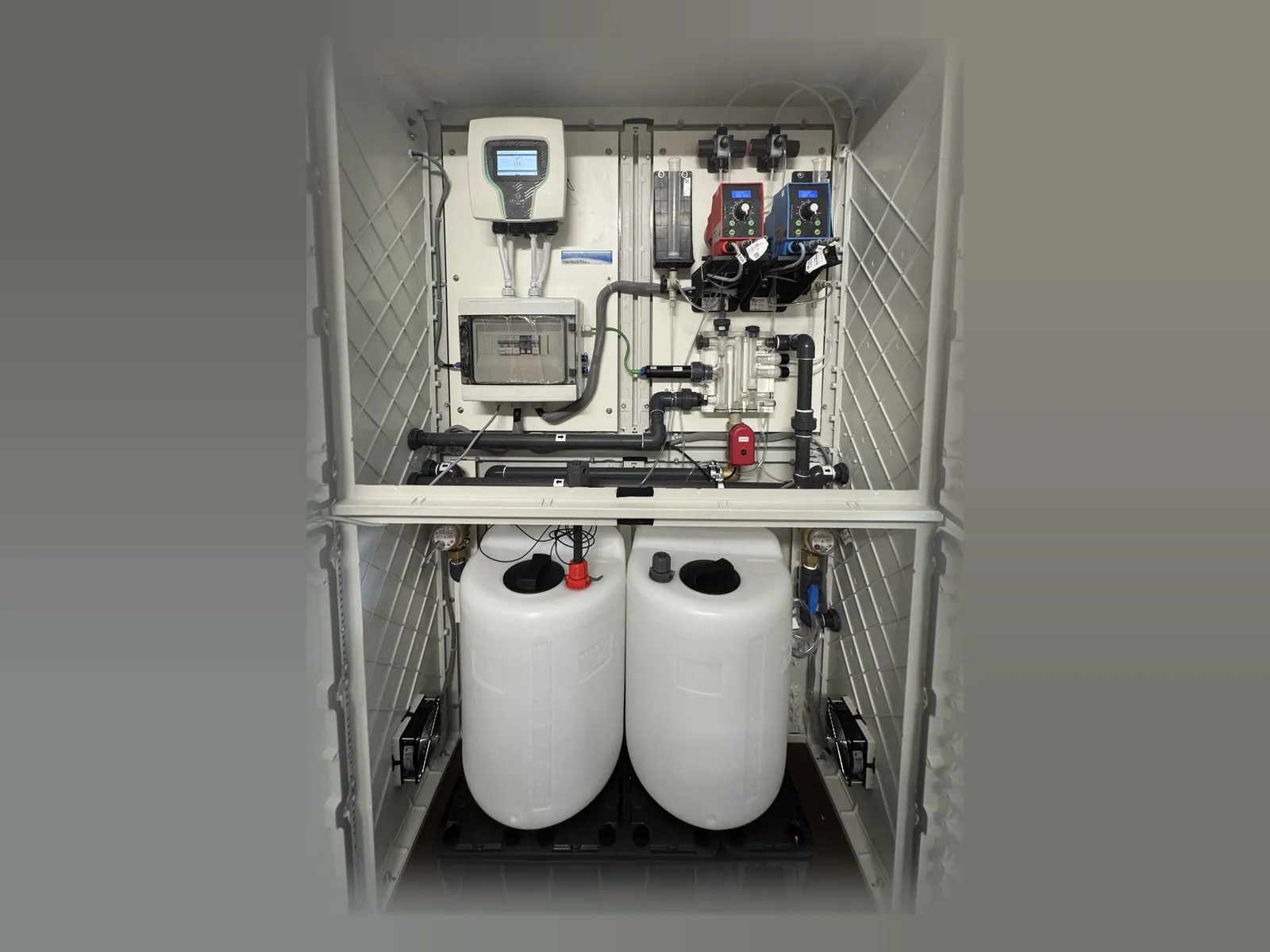
Complete solutions with controller, pumps and tanks in a cabinet.
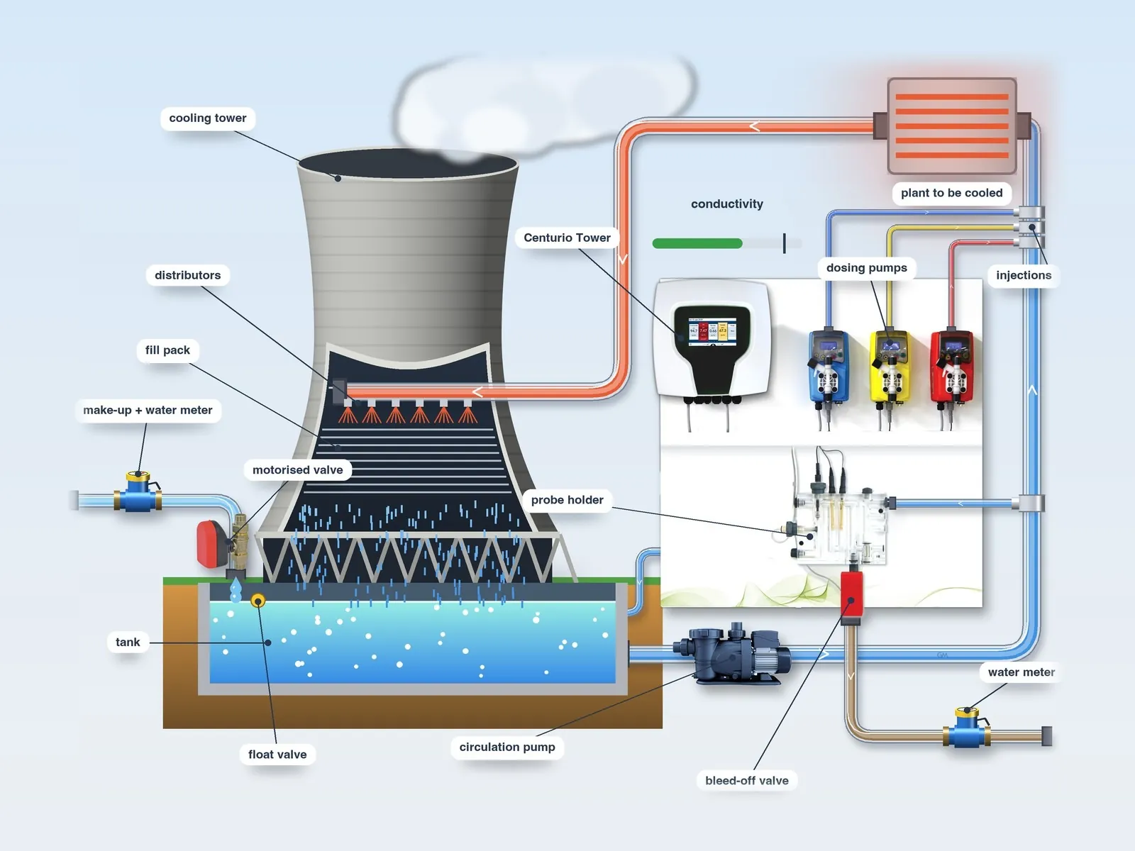
Risks, circuit, typical layout and treatment programming for cooling towers.
Systems for cooling towers →Tell us the characteristics of the tower, the parameters to be monitored and the products used: we will propose the most suitable configuration, probes and panel.
Call or write to us: a technician will reply with a tailored proposal of controllers, pumps, probes and accessories.