Generation
The turbine, installed above the storage tank, converts the pressure available in the main into electrical energy.
Installed close to a storage tank, mini-turbines use the pressure in the supply main to generate electricity, while the water continues to the tank. The energy produced powers the treatment equipment where the mains supply is not available.
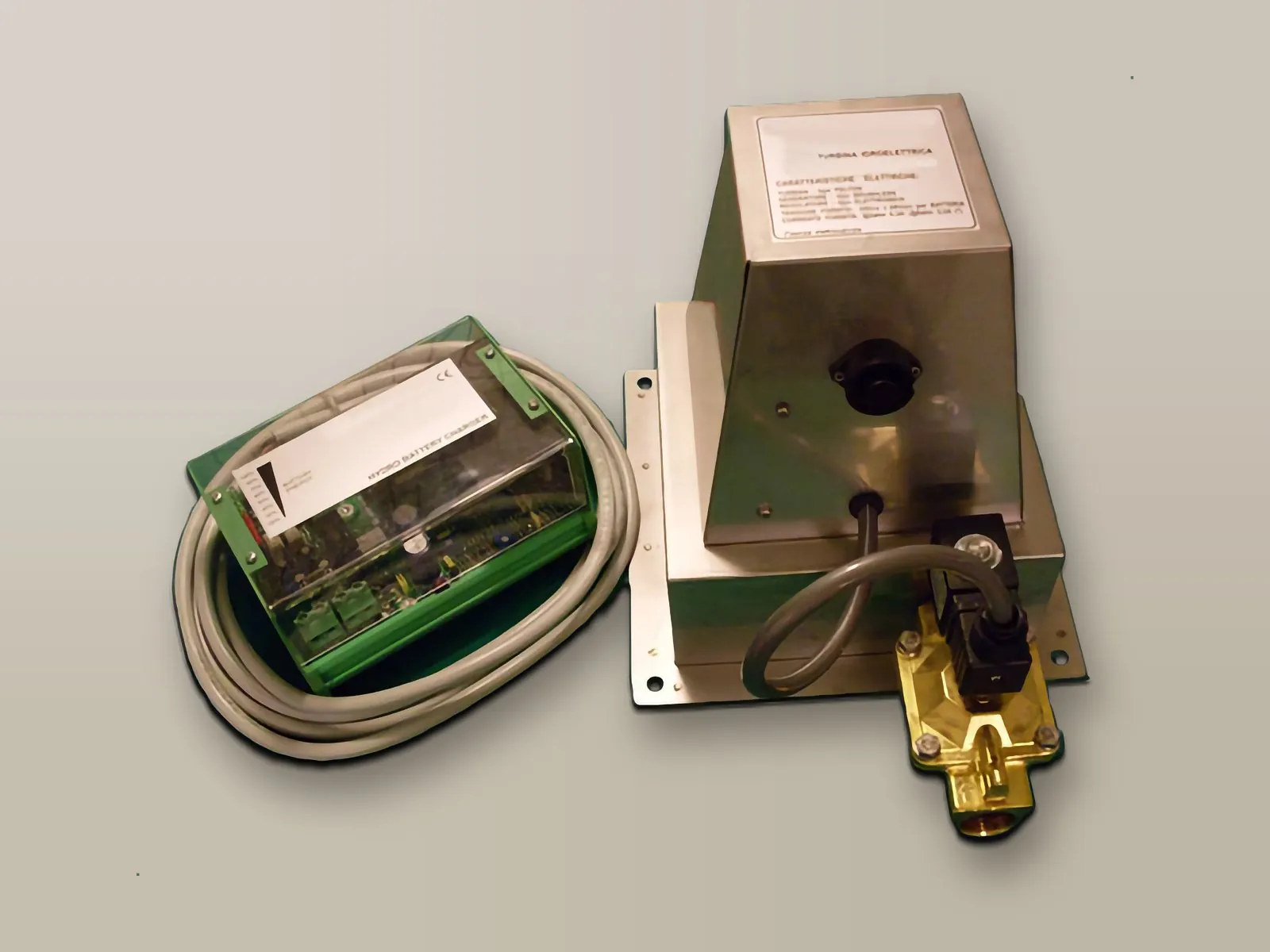
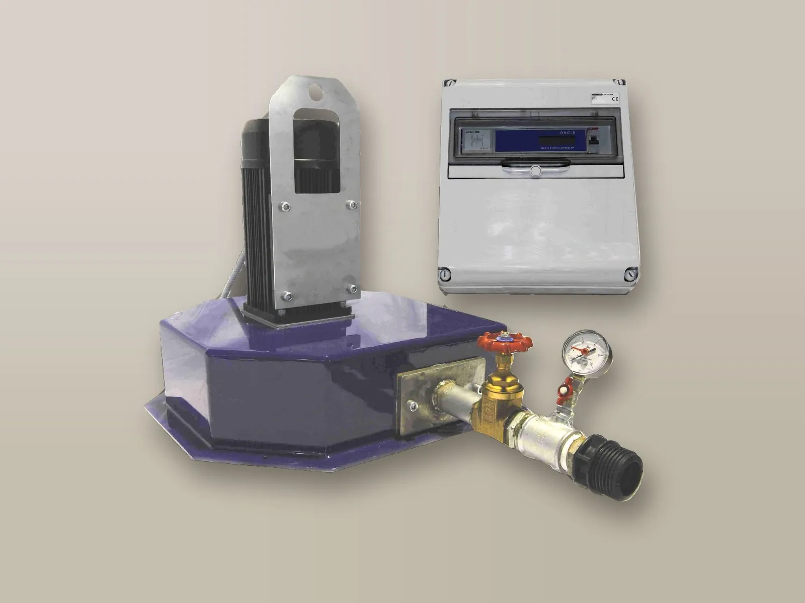
The microgenerator is driven by the pressure in the supply main: the water turns a Pelton turbine, which drives a small electric generator, and then continues to the storage tank.
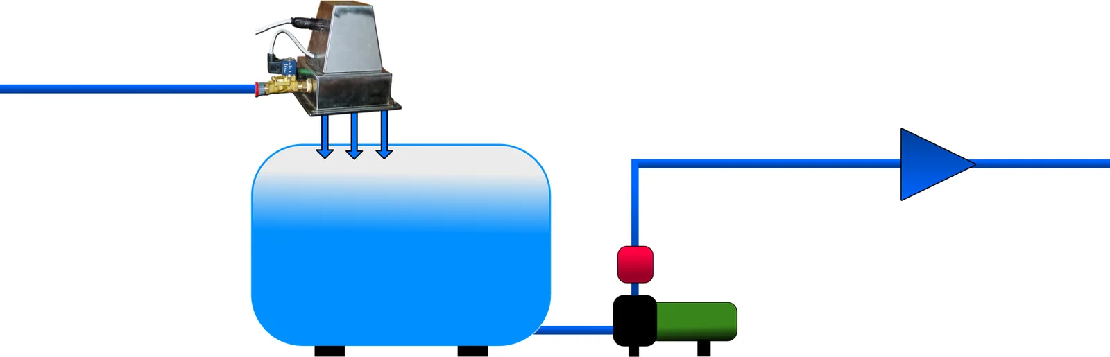
The turbine, installed above the storage tank, converts the pressure available in the main into electrical energy.
An electronic unit controls the charging of external batteries, lead-acid or 100 A AGM, the latter being particularly suited to hydroelectric applications: they charge much faster than conventional batteries and deliver over 80% of their rated current.
The treatment equipment and other loads are connected to the batteries, within the limits of the energy produced; an LED indicates the state of charge of the system.
Depending on the combination of flow rate and back pressure in the main, even outside the values in the table, the turbine is adapted (nozzle, runner, solenoid valve) to produce the maximum possible energy. Mini-turbines can be combined with a photovoltaic system.
The choice depends on the pressure and flow rate available in the main and on the voltage required by the loads.
24 VDC electronic unit (12 VDC with a dedicated converter) charging two 12 V batteries in series. When the batteries are charged the green LED stays on and, after 15 minutes, the water-saving solenoid valve shuts off the flow to the turbine, which restarts when the voltage drops. Maximum power to the charger 70 W, minimum main diameter 30 mm, 1" connections. Electronics in a DIN-rail mounted box, connection by four-core cable and safety connector.
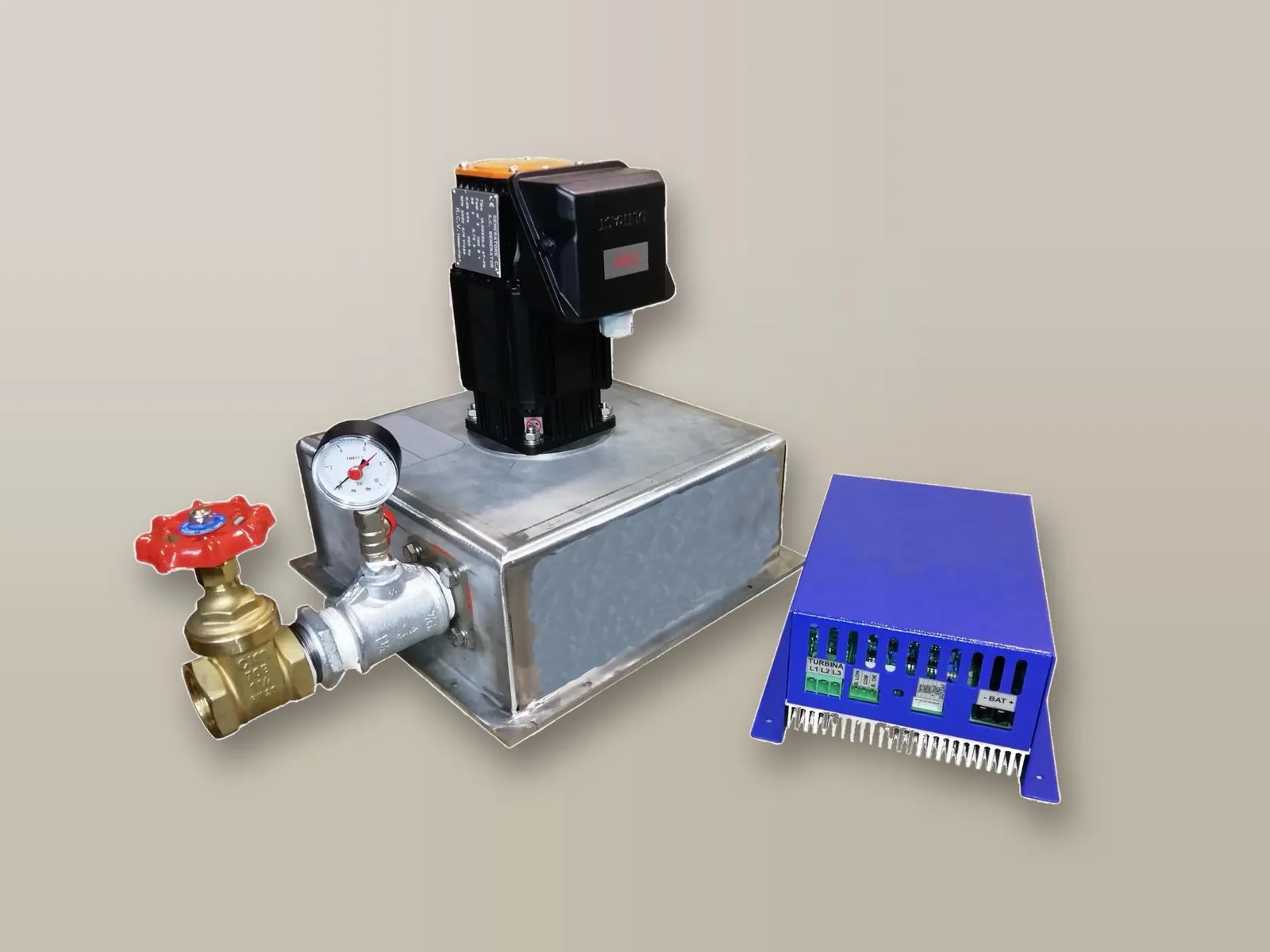
Same principle as the Small version, with 24 or 48 VDC output to be specified when ordering, stored in two or more 12 V batteries in series (two for 24 VDC, four for 48 VDC). No solenoid valve: when the batteries are charged the controller diverts the excess energy to a ballast resistor. Minimum main diameter 50 mm.
Produces over 30 kWh a day of energy at 230 VAC 50 Hz (60 Hz on request). 1.1/2" inlet, no solenoid valve; the frequency is kept stable by a DHC electronic controller that modulates a ballast resistor, supplied in a dedicated box. Seven models, from XL 1 to XL 7, according to pressure and flow rate.
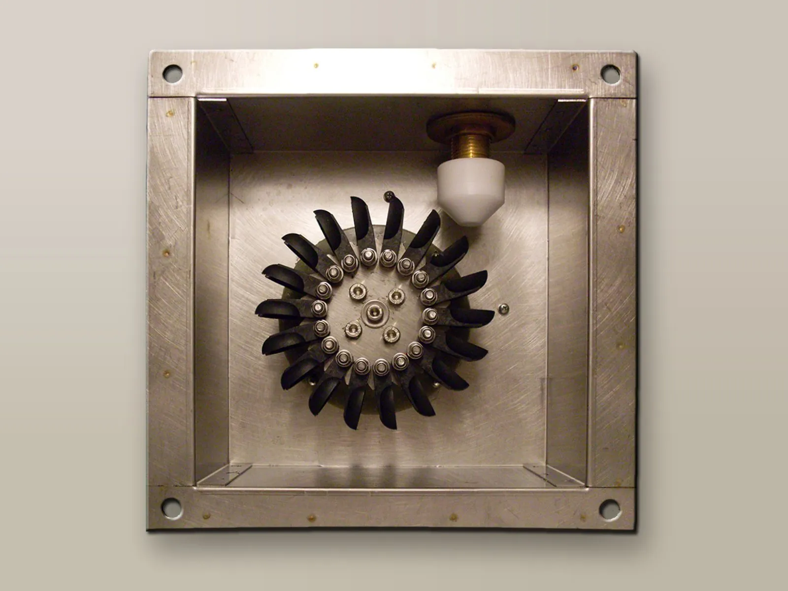
Made of materials suitable for contact with drinking water; mounting flange and connection to the main.
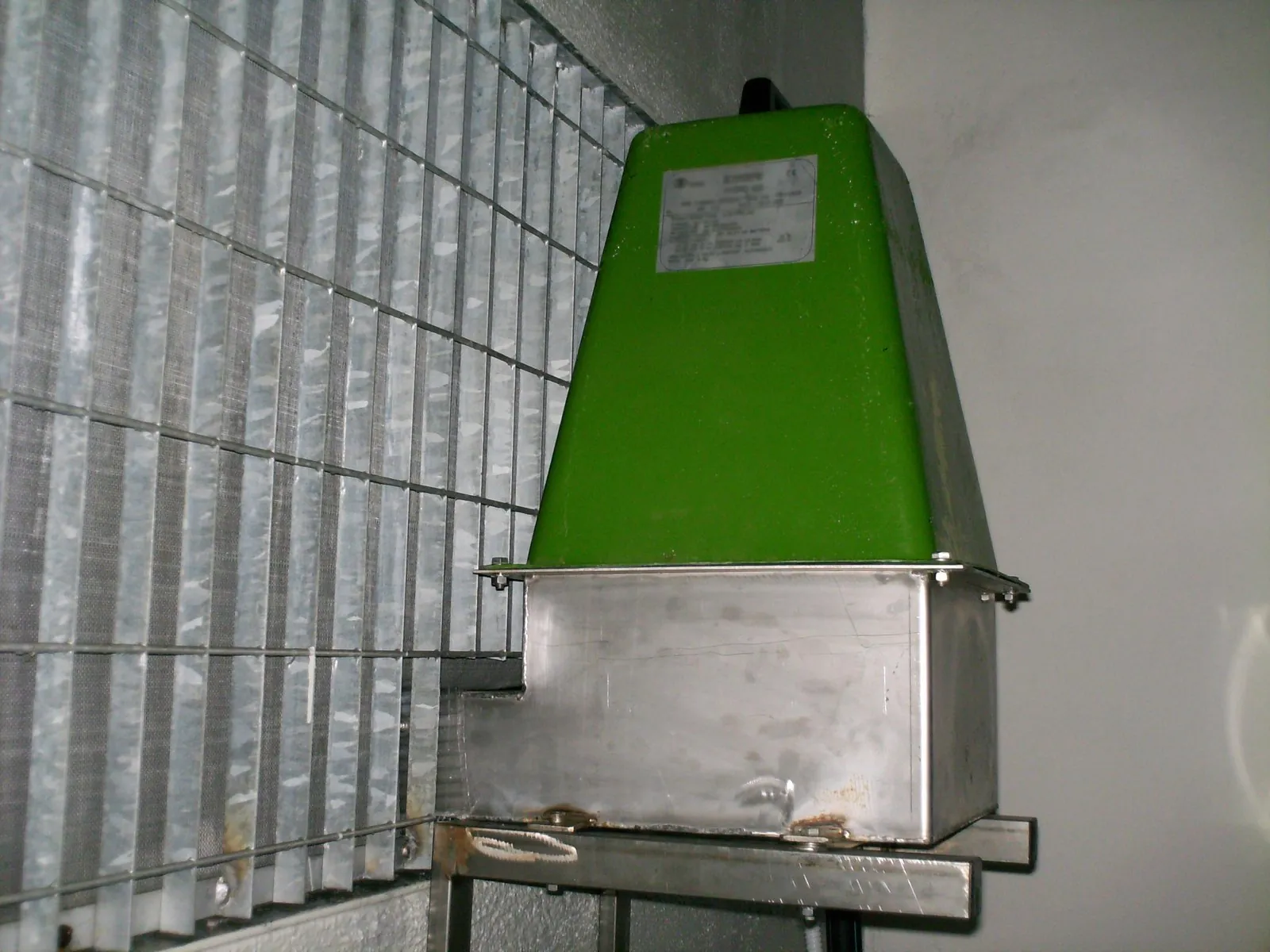
The turbine is mounted above the storage tank, into which it discharges the water after using its pressure.
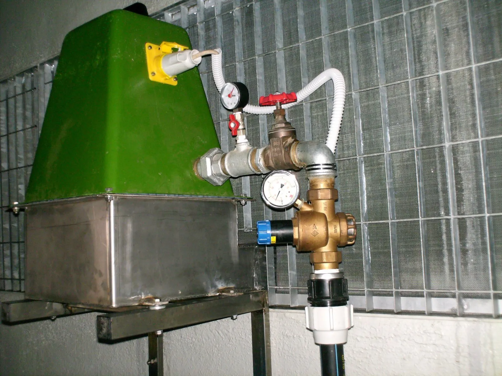
Inlet from the supply main with isolating valve and pressure gauge to check the available pressure.
Indicative values according to the pressure available in the main.
| Pressure (atm) | 2.5 | 3 | 4 | 5 | 6 |
|---|---|---|---|---|---|
| Flow rate (l/min) | 26 | 28 | 32 | 36 | 39 |
| Daily energy (Wh) | 350 | 650 | 950 | 1,500 | 2,000 |
Dimensions 240 × 240 × 250 mm (W × D × H), weight 10 kg.
| Pressure (atm) | 2 | 3 | 4 | 5 | 6 | 7 | 7.5 |
|---|---|---|---|---|---|---|---|
| Flow rate (l/s) | 0.95 | 1.05 | 1.25 | 1.4 | 1.6 | 1.7 | 1.9 |
| MPPT output power (W) | 80 | 160 | 260 | 360 | 450 | 520 | 580 |
| Daily energy (Wh) | 1,920 | 3,840 | 6,240 | 8,640 | 10,800 | 12,480 | 14,000 |
Dimensions 400 × 400 × 400 mm (W × D × H), weight 15 kg.
| Model | XL 1 | XL 2 | XL 3 | XL 4 | XL 5 | XL 6 | XL 7 |
|---|---|---|---|---|---|---|---|
| Pressure (atm) | 5 | 6 | 7 | 8 | 9.5 | 10.5 | 12 |
| Flow rate (l/s) | 4.5 | 4 | 3.3 | 2.9 | 2.5 | 2.2 | 2 |
Daily energy over 30 kWh at 230 VAC. Dimensions 560 × 560 × 600 mm (W × D × H), weight 25 kg.
Tell us the pressure and flow rate available in the main and the loads to be powered: we will propose the most suitable version, turbine configuration and batteries.
Call or write to us: a technician will reply with a tailored proposal of controllers, pumps, probes and accessories.